$DECLASSwnMfUvY5KfUN2LbKgyHXwmh39mGpJd7bjJw5A71pumpBuy
Declassified
Releases / Release 06 / DOW-UAP-D122
Department of War

AAWSAP DIRD, Invisibility Cloaking Theory and Experiments, March 2010

A 2010 Defense Intelligence Agency reference document produced under AAWSAP that surveys camouflage, transparency and metamaterial-based cloaking theory and early microwave experiments. It concludes that imperfect cloaking is feasible for microwaves, that perfect cloaking is impossible, and that visible-light cloaking is uncertain. It cites published journal literature and contains no redactions in the body.

Record
DOW-UAP-D122
Release
Release 06 · Sep 18, 2026
Incident
2010-03-02 · Las Vegas, Nevada
Pages
29
Verdict
Nothing new
Source
war.gov ↗
Context · why this verdict

This is a technical literature survey of invisibility cloaking, summarizing published academic work. Only its administrative page 2 overlaps with another AAWSAP DIRD (DOW-UAP-D118, same release), and the substance is standard published physics rather than new records about any incident.

Findings in this document

2 findings

Already public SIG

Document states single-frequency limit is an inevitable design flaw of cloaks

  • Verbatim
    The demonstrated microwave-cloaking device only works correctly for microwave radiation of a specific frequency (wavelength),
    DOW-UAP-D122 · Release 06 · page 20 · war.gov ↗
  • Context

    The 'Fundamental Problem' section describes why transformation-based cloaks do not work across multiple colors.

New or already public? The point is from published academic literature that the document itself cites (reference notes on pages 28-29).

Unclear if new SIG

DIRD concludes perfect cloaking is impossible, microwave cloaking within reach

  • Verbatim
    Perfect cloaking devices are impossible because they require materials where t he speed of light approaches infinity.
    DOW-UAP-D122 · Release 06 · page 28 · war.gov ↗
  • Verbatim
    For electromagnetic microwaves, cloaking devices are definitely within reach of the present technology.
    DOW-UAP-D122 · Release 06 · page 28 · war.gov ↗
  • Context

    The Summary page of a DIA reference document dated 2 March 2010, one of the AAWSAP DIRD series; it reviews published academic work.

  • Inference · AI interpretation

    This suggests the document is a synthesis of open scientific literature and not an original assessment of any observed phenomenon.

New or already public? No earlier archive pages match this content; however, the conclusions reflect widely published physics literature cited in the document's own references.

Page by page

The pages and what the AI read on them

The transcription is the page reader's: black bars mark what the government redacted; hatched tags mark personal data we removed.

Page 1

Page 1 of 29

This is the cover page of a Defense Intelligence Agency Defense Intelligence Reference Document titled "Invisibility Cloaking: Theory and Experiments," dated 2 March 2010 with an ICOD of 1 December 2009. The page is marked UNCLASSIFIED//FOR OFFICIAL USE ONLY and bears the DIA seal.

UNCLASSIFIED/ /FOR OFFICIAL USE ONLY Defense Intelligence Reference Document Acquisition Threat Support 2 March 2010 ICOD: 1 December 2009 DIA-08-1003-001 Invisibility Cloaking: Theory and Experiments UNCLASSIFIED/ /FOR OFFICIAL USE ONLY
Page 2

Page 2 of 29 · 1 redaction

This is the title and administrative page of a Defense Intelligence Agency report titled 'Invisibility Cloaking: Theory and Experiments', prepared by the Acquisition Support Division (DWO-3) under the AAWSA Program. It includes a copyright warning and a contact line for questions about the document.

UNCLASSIFIED//FOR OFFICIAL USE ONLY Invisibility Cloaking: Theory and Experiments Prepared by: Acquisition Support Division (DWO-3) Defense Warning Office Directorate for Analysis Defense Intelligence Agency Author: ILLEGIBLE Administrative Note COPYRIGHT WARNING: Further dissemination of the photographs in this publication is not authorized. This product is one in a series of advanced technology reports produced in FY 2009 under the Defense Intelligence Agency, Defense Warning Office's Advanced Aerospace Weapon System Applications (AAWSA) Program. Comments or questions pertaining to this document should be addressed to [REDACTED] AAWSA Program Manager, Defense Intelligence Agency, ATTN: CLAR/DWO-3, Bldg 6000, Washington, DC 20340-5100. ii UNCLASSIFIED//FOR OFFICIAL USE ONLY
Page 3

Page 3 of 29

This is the table of contents and list of figures page (page iii) of the AAWSAP DIRD report on invisibility cloaking theory and experiments. It lists chapter titles, page numbers and figure captions.

UNCLASSIFIED/ /FOR OFFICIAL USE ONLY Contents Introduction ............................................................................................................v Camouflage ............................................................................................................ 1 Transparency ......................................................................................................... 3 Cloaking ................................................................................................................. 5 Metamaterials ........................................................................................................ 9 Optical Metamaterials .......................................................................................... 11 Fundamental Problem .......................................................................................... 15 Curved Space ....................................................................................................... 17 Broadband Invisibility .......................................................................................... 19 Implementation ................................................................................................... 20 Optical Cloaking ................................................................................................... 22 Summary.............................................................................................................. 23 References ........................................................................................................... 23 Figures Figure 1. B2 Stealth Bomber .................................................................................. 1 Figure 2. Optical Camouflage ................................................................................. 2 Figure 3. The Secret Optical Camouflage ................................................................ 2 Figure 4. H. G. Wells's The Invisible Man: Invisibility by Transparency .................. 3 Figure 5. Complementary Media Invisibility Cloak .................................................. 4 Figure 6. Cloaking Shell .......................................................................................... 5 Figure 7. The Invisible Woman ............................................................................... 6 Figure 8. Fermat's Principle ................................................................................... 7 Figure 9. An Optical Material Deforms the Coordinates of Space ............................ 8 Figure 10. Light Waves at Cloaking Device ............................................................. 9 Figure 11. Cloaking Device for Microwaves .......................................................... 10 iii UNCLASSIFIED/ /FOR OFFICIAL USE ONLY
Page 4

Page 4 of 29

This is page iv, the list of figures from a report on invisibility cloaking theory and experiments, listing figures 12 through 23 with their titles and page numbers. The page carries the header and footer marking UNCLASSIFIED//FOR OFFICIAL USE ONLY, with the FOUO portion struck through.

UNCLASSIFIED//FOR OFFICIAL USE ONLY Figure 12. Lycurgus Cup (British Museum; AD Fourth Century). .......................... 11 Figure 13. Idea for a Cloaking Device for Visible Light ......................................... 12 Figure 14. Advances in Metamaterials .................................................................. 13 Figure 15. Demonstration of Negative Refraction With "Bulk" Optical Metamaterials Made of Nano-Fishnets ................................................. 14 Figure 16. Demonstration of Negative Refraction With "Bulk" Optical Metamaterials Made of Nanowires ....................................................... 15 Figure 17. Fundamental Problem of Transformation-Based Cloaking Devices ...... 16 Figure 18. Wave Packets are Made by Combining Waves With Different Frequencies. ........................................................................................ 17 Figure 19. Stereographic Projection ..................................................................... 18 Figure 20. Non-Euclidean Cloaking Device in Two Dimensions ............................. 19 Figure 21. Three-Dimensional Cloaking................................................................ 20 Figure 22. Coordinate Transformation Implemented by a Ground-Plate Cloak..... 21 Figure 23. Implementation of the Ground-Plate Cloak ......................................... 21 UNCLASSIFIED//FOR OFFICIAL USE ONLY iv UNCLASSIFIED//FOR OFFICIAL USE ONLY
Page 5

Page 5 of 29

This page is the opening Introduction of a document titled Invisibility Cloaking: Theory and Experiments, marked UNCLASSIFIED//FOR OFFICIAL USE ONLY, stating that invisibility cloaking has recently become a subject of science and technology and that the paper describes current theoretical and experimental developments.

UNCLASSIFIED/ /FOR OFFICIAL USE ONLY Invisibility Cloaking: Theory and Experiments Introduction The idea of invisibility has fascinated people for millennia, inspiring many myths, novels, and films. Invisibility cloaking has recently become a subject of science and technology. This paper describes the important current theoretical and experimental developments and tries to project into the future. V UNCLASSIFIED/ /FOR OFFICIAL USE ONLY
Page 6

Page 6 of 29

A page titled 'Camouflage' explaining that stealth aircraft use edgy shapes and special coatings to avoid radar detection, with a photograph of a B-2 stealth bomber labeled Figure 1.

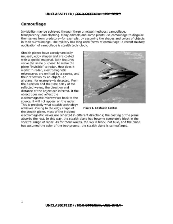
UNCLASSIFIED//FOR OFFICIAL USE ONLY Camouflage Invisibility may be achieved through three principal methods: camouflage, transparency, and cloaking. Many animals and some plants use camouflage to disguise themselves from predators emdash for example, by assuming the shapes and colors of objects in their surroundings. The military has long used forms of camouflage; a recent military application of camouflage is stealth technology. Stealth planes have aerodynamically unusual, edgy shapes and are coated with a special material. Both features serve the same purpose: to make the plane "invisible" to radar. How does it work? In radar, electromagnetic microwaves are emitted by a source, and their reflection by an object emdash an airplane, for example emdash is detected. From the direction and the time delay of the reflected waves, the direction and distance of the object are inferred. If the object does not reflect the electromagnetic microwaves back to the source, it will not appear on the radar. This is precisely what stealth technology achieves. Owing to the edgy shape of the stealth plane, most of the incident electromagnetic waves are reflected in different directions; the coating of the plane absorbs the rest. In this way, the stealth plane has become completely black in the spectral range of radar. As for radar waves, the sky is black, not blue, and the plane has assumed the color of the background: the stealth plane is camouflaged. Figure 1. B2 Stealth Bomber 1 UNCLASSIFIED//FOR OFFICIAL USE ONLY
Page 7

Page 7 of 29

Page 2 of a document describing optical camouflage developed by the University of Tokyo's Tachi Laboratory, with a photograph (Figure 2) and a labeled diagram (Figure 3) of the system. The text explains how a camera, computer, projector, half mirror and retroreflective cloak create the appearance of transparency.

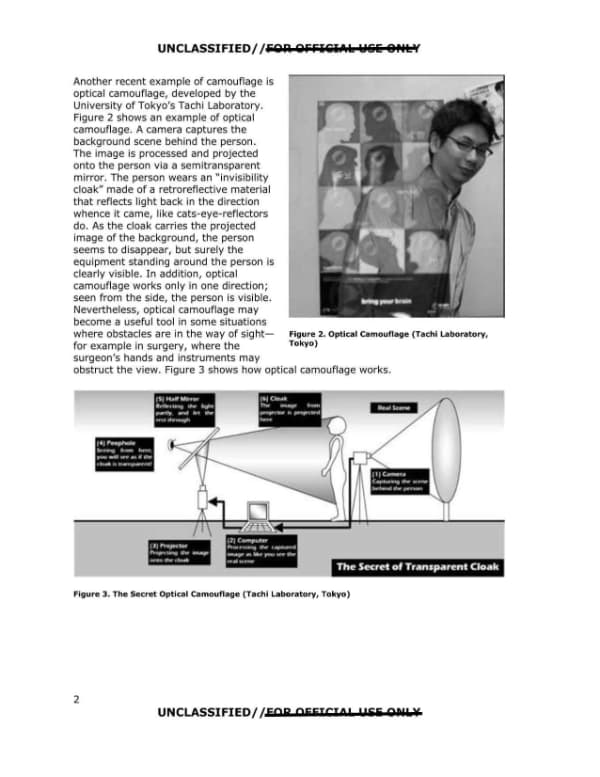
UNCLASSIFIED//FOR OFFICIAL USE ONLY Another recent example of camouflage is optical camouflage, developed by the University of Tokyo's Tachi Laboratory. Figure 2 shows an example of optical camouflage. A camera captures the background scene behind the person. The image is processed and projected onto the person via a semitransparent mirror. The person wears an "invisibility cloak" made of a retroreflective material that reflects light back in the direction whence it came, like cats-eye-reflectors do. As the cloak carries the projected image of the background, the person seems to disappear, but surely the equipment standing around the person is clearly visible. In addition, optical camouflage works only in one direction; seen from the side, the person is visible. Nevertheless, optical camouflage may become a useful tool in some situations where obstacles are in the way of sight —for example in surgery, where the surgeon's hands and instruments may obstruct the view. Figure 3 shows how optical camouflage works. [Figure 2 photograph caption: Figure 2. Optical Camouflage (Tachi Laboratory, Tokyo)] [Figure 3 diagram labels: (5) Half Mirror: Reflecting the light partly, and let the rest through; (6) Cloak: The image from projector is projected here; Real Scene; (4) Peephole: Seeing from here, you will see as if the cloak is transparent!; (1) Camera: Capturing the scene behind the person; (3) Projector: Projecting the image onto the cloak; (2) Computer: Processing the captured image as like you see the real scene; The Secret of Transparent Cloak] Figure 3. The Secret Optical Camouflage (Tachi Laboratory, Tokyo) 2 UNCLASSIFIED//FOR OFFICIAL USE ONLY
Page 8

Page 8 of 29

Page 3 of a document titled Transparency, discussing H. G. Wells's The Invisible Man and the physics of optical transparency as a route to invisibility, including proposed technological approaches. A book cover image of The Invisible Man appears with Figure 4 caption.

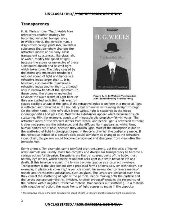
UNCLASSIFIED//FOR OFFICIAL USE ONLY Transparency H. G. Wells's novel The Invisible Man represents another strategy for becoming invisible: transparency. In Wells's novel, the invisible man, a disgruntled college professor, invents a substance that somehow changes the refractive index1 of his body. Most transparent substances, like glass, air, or water, modify the speed of light, because the atoms or molecules of these substances absorb and re-emit light, which takes time. The delay caused by the atoms and molecules results in a reduced speed of light and hence in a refractive index larger than 1. It is, however, also possible to achieve a refractive index smaller than 1, although only in narrow bands of the spectrum. In these cases, the atoms or molecules advance the wave fronts of light because they are excited such that their electron clouds oscillate ahead of the light. If the refractive index is uniform in a material, light is reflected and refracted at the boundary but otherwise is traveling straight through. On the other hand, if the refractive index varies, light is scattered at the index inhomogeneities and gets lost. Most white substances appear white because of such scattering. Milk, for example, consists of minuscule oily droplets-fat-in water. The refractive index of the droplets differs from water, and hence light is scattered at them; it does not penetrate the substance, and the diffused light appears as white. Now, human bodies are visible, because they absorb light. Most of the absorption is due to the scattering of light in biological tissue, in the cells of which the bodies are made. If the refractive indices of a person's cells could somehow be changed to the refractive index of air, the person would become transparent and disappear from view-like the Invisible Man. Some animals (for example, some jellyfish) are transparent, but the cells of higher order animals are usually much too complex and diverse for transparency to become a serious option for disguise. Exceptions are the transparent parts of the body, most notably eye lenses, which consist of uniform cells kept in a state between life and death. If this balance is upset, the lenses become opaque as a cataract develops. Transparency is the idea behind some proposed forms of invisibility by technology. For example, in plasmonic covering, 1 a particle should be surrounded by layers made of metals and transparent substances, such as glass. The layers are designed such that they cancel the scattering of light at the particle, hence making both the particle and the layers transparent-that is, invisible. Another proposal 2 exploits the resonance of the particle with a negative-refractive material that cancels out scattering. In a material with negative refraction, the wave fronts of light appear to move in the opposite 1 The refractive index is the ratio between the speed of light in vacuum and the speed of light in a material. 3 UNCLASSIFIED//FOR OFFICIAL USE ONLY
Page 9

Page 9 of 29

A journal-style page from an invisibility cloaking study describing the complementary media invisibility cloak concept and its limitations, with Figure 5 showing four panels of cloaking geometries. The page is marked UNCLASSIFIED//FOR OFFICIAL USE ONLY and is numbered page 4.
UNCLASSIFIED/ /FOR OFFICIAL USE ONLY direction from the propagation . The clearest and most advanced form of this concept is the complementary media invisibility cloak. 3 Here, an optical antiobject is placed beside the object one wishes to make disappear. The antiobject should be made of a negatively refractive material that exactly compensates the optical appearance of the object. An image is contained in the deformations of light-wave fronts caused by the imaged object. If these deformations are reversed, the image disappears, and the object becomes transparent"that is, invisible. The optical antiobject must be tailored to the object and placed precisely at the correct distance"that is, the distance where it is made to cancel the image of the object. The more complex the object is, the more complex the antiobject must be for reversing all the scatterings of light. Such cloaking at the distance cannot be instantaneous, as the light scattered by both object and antiobject must settle to a stationary state where it becomes synchronized. A stationary light field has only one color. So, in practice, these forms of transparency will work only for small objects and for small parts of the spectrum and not for large objects in many colors. [Figure 5 panel labels: a) b) c) d)] Figure 5. Complementary Media Invisibility Cloak: (a) The slab of empty space x with 0 < x < L is optically canceled by a slab of negative-index material in -L < x < 0. (b) The same cancellation effect works with an object in 0 < x < L if the negative-index slab contains an antiobject. (c) A spherical shell b < r < c is optically canceled by a negative-index shell a < r < b. If the core r < a is optically equivalent to a sphere of radius c, then this device is invisible. (d) The same as (c), but with an object in the canceled shell b < r < c. The object is cloaked: both it and the cloaking sphere are invisible. 4 UNCLASSIFIED/ /FOR OFFICIAL USE ONLY
Page 10

Page 10 of 29

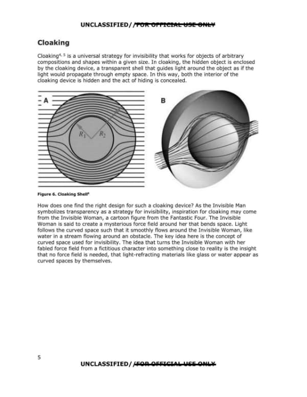
Page 5 of a report titled Cloaking, describing cloaking as a universal invisibility strategy using a transparent shell that guides light around a hidden object, with an inspiration drawn from the Invisible Woman cartoon figure. The page includes Figure 6, a cloaking shell diagram with panels A and B.

UNCLASSIFIED// FOR OFFICIAL USE ONLY Cloaking Cloaking4, 5 is a universal strategy for invisibility that works for objects of arbitrary compositions and shapes within a given size. In cloaking, the hidden object is enclosed by the cloaking device, a transparent shell that guides light around the object as if the light would propagate through empty space. In this way, both the interior of the cloaking device is hidden and the act of hiding is concealed. Figure 6. Cloaking Shell6 How does one find the right design for such a cloaking device? As the Invisible Man symbolizes transparency as a strategy for invisibility, inspiration for cloaking may come from the Invisible Woman, a cartoon figure from the Fantastic Four. The Invisible Woman is said to create a mysterious force field around her that bends space. Light follows the curved space such that it smoothly flows around the Invisible Woman, like water in a stream flowing around an obstacle. The key idea here is the concept of curved space used for invisibility. The idea that turns the Invisible Woman with her fabled force field from a fictitious character into something close to reality is the insight that no force field is needed, that light-refracting materials like glass or water appear as curved spaces by themselves. 5 UNCLASSIFIED// FOR OFFICIAL USE ONLY
Page 11

Page 11 of 29

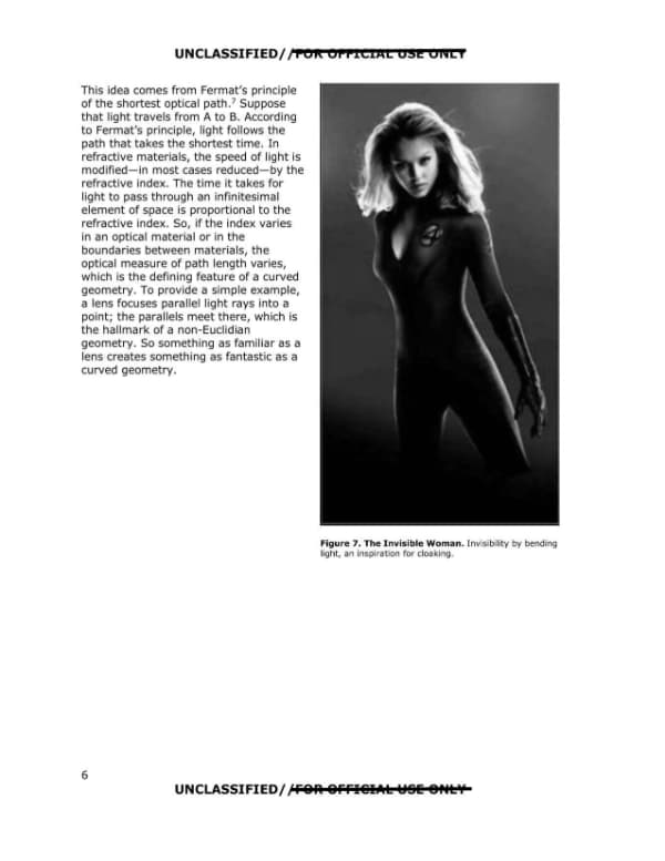
Page 6 of the document contains a passage explaining how Fermat's principle of the shortest optical path and refractive index variation produce a curved geometry, illustrated by a lens example. A photograph of a costumed character, captioned Figure 7 'The Invisible Woman', accompanies the text.

UNCLASSIFIED/ /FOR OFFICIAL USE ONLY This idea comes from Fermat's principle of the shortest optical path.7 Suppose that light travels from A to B. According to Fermat's principle, light follows the path that takes the shortest time. In refractive materials, the speed of light is modified\u2014in most cases reduced\u2014by the refractive index. The time it takes for light to pass through an infinitesimal element of space is proportional to the refractive index. So, if the index varies in an optical material or in the boundaries between materials, the optical measure of path length varies, which is the defining feature of a curved geometry. To provide a simple example, a lens focuses parallel light rays into a point; the parallels meet there, which is the hallmark of a non-Euclidian geometry. So something as familiar as a lens creates something as fantastic as a curved geometry. Figure 7. The Invisible Woman. Invisibility by bending light, an inspiration for cloaking. UNCLASSIFIED/ /FOR OFFICIAL USE ONLY 6
Page 12

Page 12 of 29

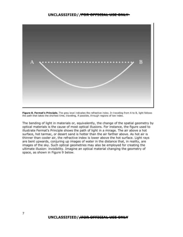
This page, numbered 7, is a printed page from an optical physics text discussing Fermat's Principle, the bending of light in materials, and mirages. It includes Figure 8, a diagram of a light path from A to B through a refractive index gradient.

UNCLASSIFIED/ /FOR OFFICIAL USE ONLY Figure 8. Fermat's Principle. The grey level indicates the refractive index. In traveling from A to B, light follows the path that takes the shortest time, traveling, if possible, through regions of low index. The bending of light in materials or, equivalently, the change of the spatial geometry by optical materials is the cause of most optical illusions. For instance, the figure used to illustrate Fermat's Principle shows the path of light in a mirage. The air above a hot surface, hot tarmac, or desert sand is hotter than the air farther above. As hot air is thinner than cooler air, the refractive index is lower above the hot surface. Light rays are bent upwards, conjuring up images of water in the distance that, in reality, are images of the sky. Such optical geometries may also be employed for creating the ultimate illusion: invisibility. Imagine an optical material changing the geometry of space, as shown in Figure 9 below. UNCLASSIFIED/ /FOR OFFICIAL USE ONLY 7 UNCLASSIFIED/ /FOR OFFICIAL USE ONLY