$DECLASSwnMfUvY5KfUN2LbKgyHXwmh39mGpJd7bjJw5A71pumpBuy
Declassified
Releases / Release 06 / DOW-UAP-D122
Department of War

AAWSAP DIRD, Invisibility Cloaking Theory and Experiments, March 2010

A 2010 Defense Intelligence Agency reference document produced under AAWSAP that surveys camouflage, transparency and metamaterial-based cloaking theory and early microwave experiments. It concludes that imperfect cloaking is feasible for microwaves, that perfect cloaking is impossible, and that visible-light cloaking is uncertain. It cites published journal literature and contains no redactions in the body.

Record
DOW-UAP-D122
Release
Release 06 · Sep 18, 2026
Incident
2010-03-02 · Las Vegas, Nevada
Pages
29
Verdict
Nothing new
Source
war.gov ↗
Context · why this verdict

This is a technical literature survey of invisibility cloaking, summarizing published academic work. Only its administrative page 2 overlaps with another AAWSAP DIRD (DOW-UAP-D118, same release), and the substance is standard published physics rather than new records about any incident.

Findings in this document

2 findings

Already public SIG

Document states single-frequency limit is an inevitable design flaw of cloaks

  • Verbatim
    The demonstrated microwave-cloaking device only works correctly for microwave radiation of a specific frequency (wavelength),
    DOW-UAP-D122 · Release 06 · page 20 · war.gov ↗
  • Context

    The 'Fundamental Problem' section describes why transformation-based cloaks do not work across multiple colors.

New or already public? The point is from published academic literature that the document itself cites (reference notes on pages 28-29).

Unclear if new SIG

DIRD concludes perfect cloaking is impossible, microwave cloaking within reach

  • Verbatim
    Perfect cloaking devices are impossible because they require materials where t he speed of light approaches infinity.
    DOW-UAP-D122 · Release 06 · page 28 · war.gov ↗
  • Verbatim
    For electromagnetic microwaves, cloaking devices are definitely within reach of the present technology.
    DOW-UAP-D122 · Release 06 · page 28 · war.gov ↗
  • Context

    The Summary page of a DIA reference document dated 2 March 2010, one of the AAWSAP DIRD series; it reviews published academic work.

  • Inference · AI interpretation

    This suggests the document is a synthesis of open scientific literature and not an original assessment of any observed phenomenon.

New or already public? No earlier archive pages match this content; however, the conclusions reflect widely published physics literature cited in the document's own references.

Page by page

The pages and what the AI read on them

The transcription is the page reader's: black bars mark what the government redacted; hatched tags mark personal data we removed.

Page 13

Page 13 of 29

A page from a report on invisibility cloaking theory, containing Figure 9 and a passage explaining how an optical material deforms the coordinates of space to make enclosed objects invisible. The figure is a two-panel diagram of virtual and real space.

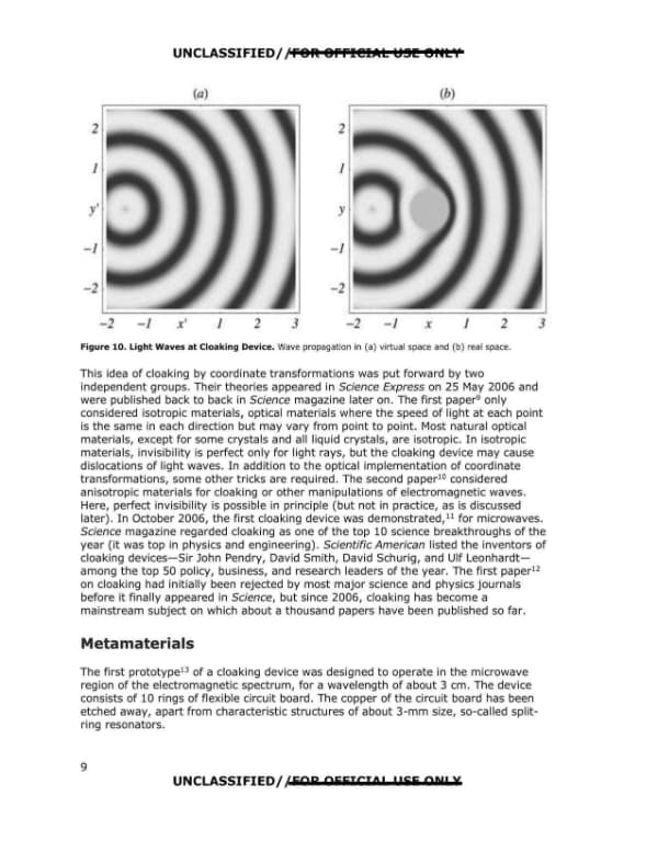
UNCLASSIFIED//FOR OFFICIAL USE ONLY Figure 9. An Optical Material Deforms the Coordinates of Space. A: virtual space, B: real space. The material acts like a transformation of space. In the device, each point in real space is put to a new location in a virtual space (outside of the device, space remains the same). The device creates the illusion that light propagates along straight lines through the virtual space, whereas in reality it is bent. Suppose the device encloses a hollow region that is not part of the virtual space or, to be more precise, a region with a surface that, in virtual space, has become a single point. The red circle in Figure 9B is reduced to the red dot in Figure 9A. As the hollow region is not part of the virtual space where light propagates, everything inside it has become invisible. As the coordinates of virtual space smoothly go over into the coordinates of real space at the outer surface of the device, light rays are not distorted. Any object inside the cloaking device is hidden, and so is the act of hiding itself. Moreover, the cloaking device not only would bend light rays but would modify the entire structure of light waves in such a way that detecting the hidden object is impossible. Light waves would advance around the hidden core of the device, engulfing it, as Figure 10 shows.8 8 UNCLASSIFIED//FOR OFFICIAL USE ONLY
Page 14

Page 14 of 29

Page 9 of a declassification-marked report on invisibility cloaking theory, covering the 2006 coordinate-transformation papers and the start of a section on metamaterials. A figure shows light wave propagation in virtual and real space around a cloaking device.

UNCLASSIFIED/,'FOR: OFFl@IAL l!ISI!!! 9HLY Figure 10. Light Waves at Cloaking Device. Wave propagation in (a) virtual space and (b) real space. This idea of cloaking by coordinate transformations was put forward by two independent groups. Their theories appeared in Science Express on 25 May 2006 and were published back to back in Science magazine later on. The first paper9 only considered isotropic materials, optical materials where the speed of light at each point is the same in each direction but may vary from point to point. Most natural optical materials, except for some crystals and all liquid crystals, are isotropic. In isotropic materials, invisibility is perfect only for light rays, but the cloaking device may cause dislocations of light waves. In addition to the optical implementation of coordinate transformations, some other tricks are required. The second paper10 considered anisotropic materials for cloaking or other manipulations of electromagnetic waves. Here, perfect invisibility is possible in principle (but not in practice, as is discussed later). I n October 2006, the first cloaking device was demonstrated, 11 for microwaves. Science magazine regarded cloaking as one of the top 10 science breakthroughs of the year (it was top in physics and engineering) . Scientific American listed the inventors of cloaking devices-Sir John Pendry, David Smith, David Schurig, and Ulf Leonhardtamong the top 50 policy, business, and research leaders of the year. The first paper12 on cloaking had initially been rejected by most major science and physics journals before it finally appeared in Science, but since 2006, cloaking has become a mainstream subject on which about a thousand papers have been published so far. Metamaterials The first prototype13 of a cloaking device was designed to operate in the microwave region of the electromagnetic spectrum, for a wavelength of about 3 cm. The device consists of 10 rings of flexible circuit board. The copper of the circuit board has been etched away, apart from characteristic structures of about 3-mm size, so-called splitring resonators. UNCLASSIFIED//509 OFFICIOP 1!55 ODtf PX 9 UNCLASSIFIED/ /FOR OFFICIAL USE ONLY
Page 15

Page 15 of 29

A page of a 2010 AAWSAP DIRD report on invisibility cloaking theory explaining how split-ring resonators act as metamaterials in a microwave cloaking device, with a comparison to the gold particles in ancient Roman ruby glass. Figure 11, a cloaking device for microwaves, appears on the page.

UNCLASSIFIED//FOR OFFICIAL USE ONLY The split-ring resonators are electromagnetic circuits; they respond to the electromagnetic field of microwave radiation. Their response depends on their shapes. For example, in the cloaking device shown in Figure 11, the double stripes in the middle of the split-ring resonators vary from ring to ring. As these stripes form an electric capacitor, the capacitance of the resonators also varies. The colored curves show how the electromagnetic functions change over the distance from the center of the cloaking device as a result of the varied capacitance. As they are always positive, negative refraction is not required for cloaking. At the inner ring, the red curve reaches zero, defining the boundary of the cloaking device. The rings with their split-ring structures are designed to perform an approximation of the coordinate transformation shown and explained in the previous section. How is this possible? The split-ring resonators act like the atoms or molecules of a normal optical or electromagnetic material: they absorb electromagnetic waves and re-emit them with a phase delay or advance that depends on their electromagnetic response. Like atoms or molecules, they are much smaller than the electromagnetic wavelength\u2014 3-mm cell size versus 3-cm wavelength in the case of the microwave cloaking device15\u2014such that the waves cannot resolve them individually but, rather, react to them as if they were a bulk material with electromagnetic properties that may differ from point to point. Unlike atoms or molecules, the electromagnetic response of each split-ring resonator is tailormade because it depends on the shape of the resonator that can be easily modified. For example, in the case of the microwave-cloaking device,16 the electromagnetic response depends on the capacitance that is varied by changing the length of the double stripes in the resonators. An unstructured circuit board reacts completely differently to the microwave radiation: it would simply reflect it like the mesh in the window of a microwave oven. A material with electromagnetic or optical properties that depends on structures much smaller than the wavelength is called a metamaterial. Metamaterials per se are nothing new; the ancient Romans invented the first optical metamaterial: ruby glass. The Romans probably did not know it, but their recipe for ruby glass contained one crucial ingredient:17 tiny gold droplets, typically 5-60 nanometers (nm) in size. These gold particles color the glass in an extraordinary way, as demonstrated by the exquisite Lycurgus Cup shown in Figure 12. In daylight, the cup appears a greenish color, but illuminate it from the inside, and it glows ruby. The gold particles act like the split-ring resonators of the microwave-cloaking device,18 but here on light, not on microwave radiation. Light consists of electromagnetic waves as well, but with significantly smaller wavelengths of around 500 nm. The gold particles are thus much smaller than the wavelength of light, and they turn out to be resonators as well: in them, electric currents flow in a way that is dictated by their shapes and sizes. When the light wave hits the resonance of the gold particle, most of its energy is UNCLASSIFIED//FOR OFFICIAL USE ONLY 10 UNCLASSIFIED//FOR OFFICIAL USE ONLY
Page 16

Page 16 of 29

Page 11 of a report on invisibility cloaking discusses how the gold particles in the Lycurgus Cup cause its ruby color and introduces optical metamaterials, explaining why microwave cloaking designs do not simply scale down to visible light. The page includes a figure caption describing the Lycurgus Cup.

converted into the electromagnetic oscillation of the gold particle in much the same way a tuning fork responds to sound of the right frequency . However, the electromagnetic oscillation is damped out by the electric resistance in the metal, and its energy is absorbed and ultimately turned into heat. The color of light corresponds to the frequency or wavelength. If one of the frequencies is absorbed, the corresponding color is missing in the spectrum. For the gold particles in the Lycurgus Cup, this color is green; a spectrum with green missing appears red, which produces the cup's exquisite color. (Light is also scattered in the material, and this scattering is enhanced near the green of the resonance; hence the greenish color of the cup seen in daylight.) What is new about metamaterials is the degree of control on their structures achieved by applying modern technology and the level of theoretical Figure 12. Lycurgus Cup (British Museum; fourth century AD). This Roman cup is made of ruby glass. When viewed in reflected light- for example, in daylightit appears green. However, when a light is shone into the cup and transmitted through the glass, it appears red. The cup illustrates the myth of King Lycurgus. He is seen being dragged into the underworld by the Greek nymph Ambrosia, who is disguised as a vine. understanding of their workings. The Romans most probably never understood why ruby glass is neither golden like gold nor transparent like glass, its ingredients, but ruby. They did not know that light is an electromagnetic wave, nor did they know the basic laws of electromagnetism. And they would not have had the technological tools to use this knowledge in the design of novel optical metamaterials. Optical Metamaterials As light is simply an electromagnetic wave with shorter wavelengths than microwave radiation, one could imagine an optical cloaking device as the microwave cloak but with much smaller cells, fitted to the smaller wavelength. However, this simple idea is too simple, for two different reasons. One is that metals like the copper of the circuit board or the gold of ruby glass are more electrically resistant to currents oscillating with the frequency of visible light than to currents in the microwave range of the spectrum. Second, and more important, the cells of a metamaterial also emit electromagnetic radiation in an incoherent way, not just as a coherent response to the incoming electromagnetic wave, similar to the spontaneous emission of light by atoms and molecules. The spontaneous emission is significantly stronger in the optical range of the spectrum. In short, metamaterials do not scale; they must be designed differently for visible light, and the loss of light by absorption and incoherent scattering usually is greater for visible light than for microwaves. Figure 13 below illustrates the idea19 for an optical cloaking metamaterial. Instead of split-ring resonators, nano-scale metal wires are embedded in a transparent host material, for example glass. The wires replace the split-ring resonators on the circuit board of the microwave-cloaking device. They act similarly to the gold particles embedded in ruby glass; their optical properties 11
Page 17

Page 17 of 29

This page, a figure-bearing page of an AAWSAP DIRD report on invisibility cloaking, describes a conceptual optical cloaking device using metal nanowires in place of split-ring resonators and includes Figure 13 with coordinate transformation diagrams. The text states that such optical cloaking devices do not yet exist.

depend on their lengths and on their arrangement, which, in principle, can be tailor-made and controlled using the tools of modern nanotechnology. The thin wires will have lower electric losses than split-ring resonators, and their radiation losses by the equivalent of spontaneous emission are reduced as well. Such optical cloaking devices do not yet exist, but one can gauge the progress in the required technology by considering the progress in negatively refracting optical materials. Figure 13. Idea for a Cloaking Device for Visible Light. Metal nanowires replace the split-ring resonators of the microwave cloaking device. Coordinate transformation and structure of the optical cloak. a: The coordinate transformation that compresses a cylindrical region r < b into a concentric cylindrical shell a < r < b. There is no variation along the vertical direction. The radii r1 and r2 define the internal and external radius of a fraction of the cylindrical cloak. b: A small fraction of the cylindrical cloak. The wires are all perpendicular to the cylinder's inner and outer interfaces, but their spatial positions do not have to be periodic and can be random.20 Figure 14 below21 illustrates the route toward achieving negative refraction in the visible range of the spectrum. Losses typically are a greater problem for negatively
Page 18

Page 18 of 29

Page 13 of the report discusses advances in metamaterials for optical cloaking, with a labeled chart (Figure 14) plotting magnetic resonance frequency against year from 2000 to 2007 and four inset images of fabricated structures. The text states that cloaking devices require bulk metamaterials with varying cell structures and that the most severe practical problem is a problem at the core of their principal design.

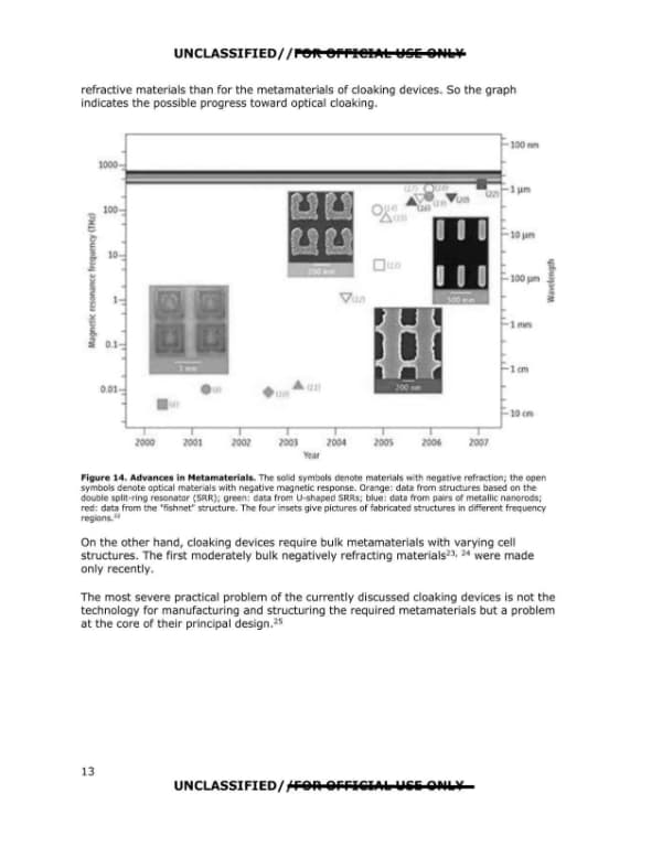
UNCLASSIFIED//FOR OFFICIAL USE ONLY refractive materials than for the metamaterials of cloaking devices. So the graph indicates the possible progress toward optical cloaking. [Figure 14 chart: Magnetic resonance frequency (THz) vs. Year 2000-2007, with wavelength scale on right; four inset images of fabricated structures] Figure 14. Advances in Metamaterials. The solid symbols denote materials with negative refraction; the open symbols denote optical materials with negative magnetic response. Orange: data from structures based on the double split-ring resonator (SRR); green: data from U-shaped SRRs; blue: data from pairs of metallic nanorods; red: data from the "fishnet" structure. The four insets give pictures of fabricated structures in different frequency regions.22 On the other hand, cloaking devices require bulk metamaterials with varying cell structures. The first moderately bulk negatively refracting materials23, 24 were made only recently. The most severe practical problem of the currently discussed cloaking devices is not the technology for manufacturing and structuring the required metamaterials but a problem at the core of their principal design.25 13 UNCLASSIFIED//FOR OFFICIAL USE ONLY
Page 19

Page 19 of 29

This page presents Figure 15, a diagram panel set showing a demonstration of negative refraction using bulk optical metamaterials made of nano-fishnets, with panels a (electron micrograph of a fishnet structure), b (prism refraction geometry with n=1 and n<0 rays), and c (optical setup with lenses, sample, camera and resulting image). The page is otherwise blank apart from the figure caption and page number.

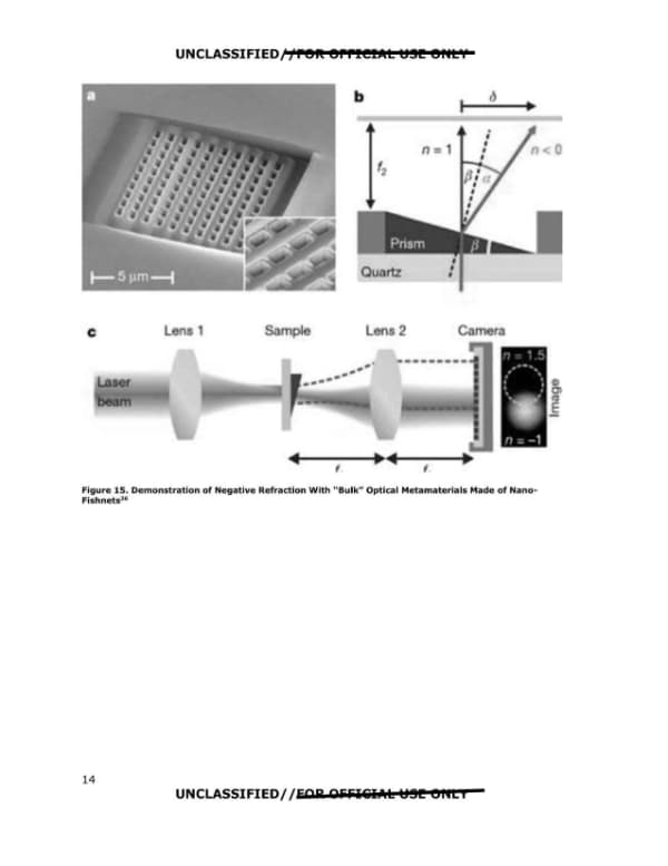
UNCLASSIFIED//FOR OFFICIAL USE ONLY Figure 15. Demonstration of Negative Refraction With "Bulk" Optical Metamaterials Made of Nano-Fishnets26 UNCLASSIFIED//FOR OFFICIAL USE ONLY 14 UNCLASSIFIED//FOR OFFICIAL USE ONLY Figure 15. Demonstration of Negative Refraction With "Bulk" Optical Metamaterials Made of Nano-Fishnets26
Page 20

Page 20 of 29

This page is a report page containing a figure caption for a negative refraction demonstration with optical metamaterials made of nanowires, followed by a section titled "Fundamental Problem" describing a design limitation of cloaking devices. The text states that the cloaking devices work only for a single frequency and that light of other colors would be distorted.

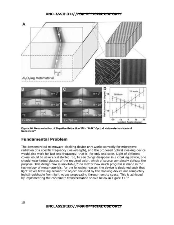
UNCLASSIFIED//FOR OFFICIAL USE ONLY Figure 16. Demonstration of Negative Refraction With "Bulk" Optical Metamaterials Made of Nanowires27 Fundamental Problem The demonstrated microwave-cloaking device only works correctly for microwave radiation of a specific frequency (wavelength), and the proposed optical cloaking device would also work for just one frequency; that is, for only one color. Light of different colors would be severely distorted. So, to see things disappear in a cloaking device, one should wear tinted glasses of the required color, which of course completely defeats the purpose. This design flaw is inevitable,28 no matter how much progress is made in the technology of metamaterials, for the following reason: the device is designed such that light waves traveling around the object enclosed by the cloaking device are completely indistinguishable from light waves propagating through empty space. This is achieved by implementing the coordinate transformation shown below in Figure 17.29 15 UNCLASSIFIED//FOR OFFICIAL USE ONLY
Page 21

Page 21 of 29

Page 16 of the AAWSAP DIRD report on invisibility cloaking theory, containing Figure 17 (a diagram of virtual and real space for a transformation-based cloak) and explanatory text on light speed, phase velocity and group velocity.

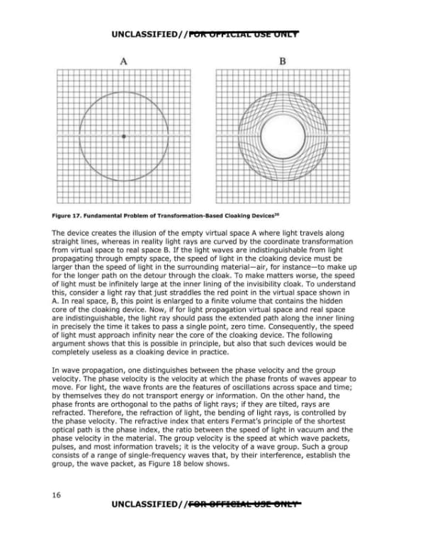
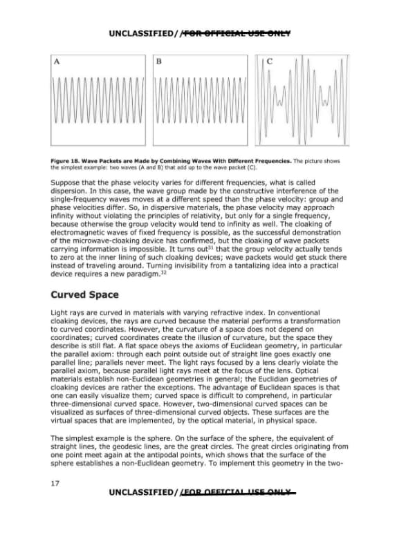
UNCLASSIFIED//FOR OFFICIAL USE ONLY Figure 17. Fundamental Problem of Transformation-Based Cloaking Devices30 The device creates the illusion of the empty virtual space A where light travels along straight lines, whereas in reality light rays are curved by the coordinate transformation from virtual space to real space B. If the light waves are indistinguishable from light propagating through empty space, the speed of light in the cloaking device must be larger than the speed of light in the surrounding material—air, for instance—to make up for the longer path on the detour through the cloak. To make matters worse, the speed of light must be infinitely large at the inner lining of the invisibility cloak. To understand this, consider a light ray that just straddles the red point in the virtual space shown in A. In real space, B, this point is enlarged to a finite volume that contains the hidden core of the cloaking device. Now, if for light propagation virtual space and real space are indistinguishable, the light ray should pass the extended path along the inner lining in precisely the time it takes to pass a single point, zero time. Consequently, the speed of light must approach infinity near the core of the cloaking device. The following argument shows that this is possible in principle, but also that such devices would be completely useless as a cloaking device in practice. In wave propagation, one distinguishes between the phase velocity and the group velocity. The phase velocity is the velocity at which the phase fronts of waves appear to move. For light, the wave fronts are the features of oscillations across space and time; by themselves they do not transport energy or information. On the other hand, the phase fronts are orthogonal to the paths of light rays; if they are tilted, rays are refracted. Therefore, the refraction of light, the bending of light rays, is controlled by the phase velocity. The refractive index that enters Fermat's principle of the shortest optical path is the phase index, the ratio between the speed of light in vacuum and the phase velocity in the material. The group velocity is the speed at which wave packets, pulses, and most information travels; it is the velocity of a wave group. Such a group consists of a range of single-frequency waves that, by their interference, establish the group, the wave packet, as Figure 18 below shows. 16 UNCLASSIFIED//FOR OFFICIAL USE ONLY
Page 22

Page 22 of 29

Page 17 of a declassified AAWSAP report on invisibility cloaking theory, covering wave packets and dispersion, and beginning a section titled Curved Space. The page includes a figure showing two waves (A and B) combining into a wave packet (C).

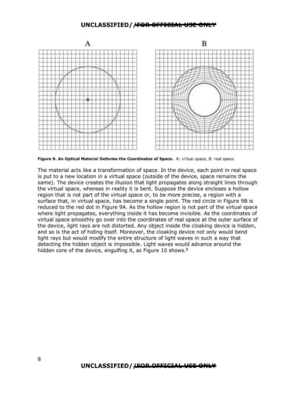
UNCLASSIFIED/,'FOR: OFFl@IAL l!ISl!!! 9HLY A B C Figure 18. Wave Packets are Made by Combining Waves With Different Frequencies. The picture shows the simplest example: two waves (A and B) that add up to the wave packet (C). Suppose that the phase velocity varies for different frequencies, what is called dispersion. In this case, the wave group made by the constructive interference of the single-frequency waves moves at a different speed than the phase velocity: group and phase velocities differ. So, in dispersive materials, the phase velocity may approach infinity without violating the principles of relativity, but only for a single frequency, because otherwise the group velocity would tend to infinity as well. The cloaking of electromagnetic waves of fixed frequency is possible, as the successful demonstration of the microwave-cloaking device has confirmed, but the cloaking of wave packets carrying information is impossible. It turns out31 that the group velocity actually tends to zero at the inner lining of such cloaking devices; wave packets would get stuck there instead of traveling around. Turning invisibility from a tantalizing idea into a practical device requires a new paradigm.32 Curved Space Light rays are curved in materials with varying refractive index. In conventional cloaking devices, the rays are curved because the material performs a transformation to curved coordinates. However, the curvature of a space does not depend on coordinates; curved coordinates create the illusion of curvature, but the space they describe is still flat. A flat space obeys the axioms of Euclidean geometry, in particular the parallel axiom: through each point outside out of straight line goes exactly one parallel line; parallels never meet. The light rays focused by a lens clearly violate the parallel axiom, because parallel light rays meet at the focus of the lens. Optical materials establish non-Euclidean geometries in general; the Euclidian geometries of cloaking devices are rather the exceptions. The advantage of Euclidean spaces is that one can easily visualize them; curved space is difficult to comprehend, in particular three-dimensional curved space. However, two-dimensional curved spaces can be visualized as surfaces of three-dimensional curved objects. These surfaces are the virtual spaces that are implemented, by the optical material, in physical space. The simplest example is the sphere. On the surface of the sphere, the equivalent of straight lines, the geodesic lines, are the great circles. The great circles originating from one point meet again at the antipodal points, which shows that the surface of the sphere establishes a non-Euclidean geometry. To implement this geometry in the two-UNCLASSIFIED/ /EAR OFFICIO! I 155 ONL¥ 17 UNCLASSIFIED/ /FOR OFFICIAL USE ONLY
Page 23

Page 23 of 29

A printed page from an unclassified report on invisibility cloaking theory, discussing stereographic projection and Maxwell's fisheye lens, with Figure 19 showing a stereographic projection of a sphere onto a plane. The page is numbered 18 and marked For Official Use Only.

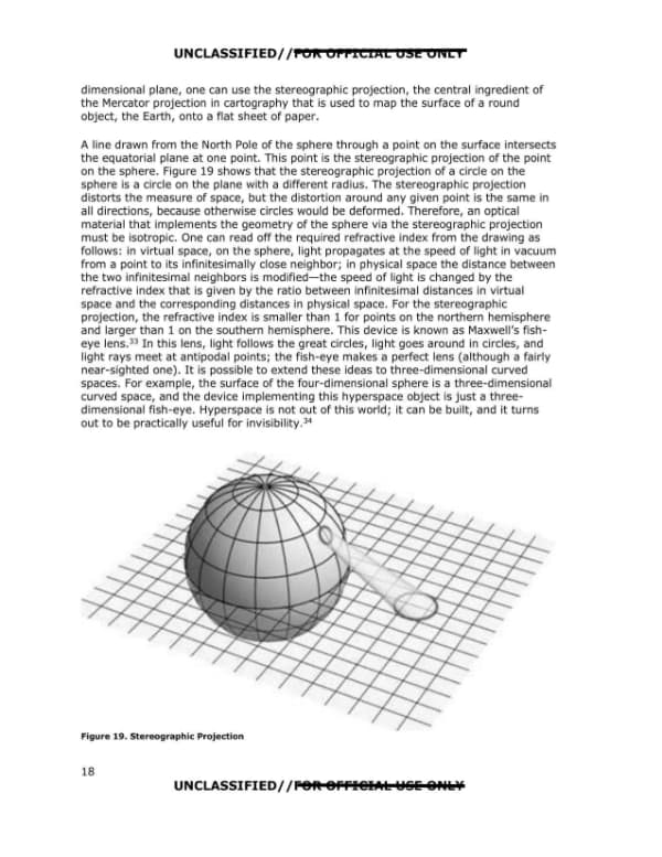
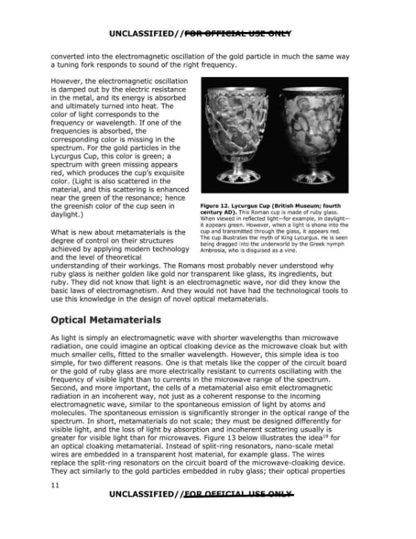
UNCLASSIFIED//FOR OFFICIAL USE ONLY dimensional plane, one can use the stereographic projection, the central ingredient of the Mercator projection in cartography that is used to map the surface of a round object, the Earth, onto a flat sheet of paper. A line drawn from the North Pole of the sphere through a point on the surface intersects the equatorial plane at one point. This point is the stereographic projection of the point on the sphere. Figure 19 shows that the stereographic projection of a circle on the sphere is a circle on the plane with a different radius. The stereographic projection distorts the measure of space, but the distortion around any given point is the same in all directions, because otherwise circles would be deformed. Therefore, an optical material that implements the geometry of the sphere via the stereographic projection must be isotropic. One can read off the required refractive index from the drawing as follows: in virtual space, on the sphere, light propagates at the speed of light in vacuum from a point to its infinitesimally close neighbor; in physical space the distance between the two infinitesimal neighbors is modified-the speed of light is changed by the refractive index that is given by the ratio between infinitesimal distances in virtual space and the corresponding distances in physical space. For the stereographic projection, the refractive index is smaller than 1 for points on the northern hemisphere and larger than 1 on the southern hemisphere. This device is known as Maxwell's fisheye lens. 33 In this lens, light follows the great circles, light goes around in circles, and light rays meet at antipodal points; the fish-eye makes a perfect lens (although a fairly near-sighted one). It is possible to extend these ideas to three-dimensional curved spaces. For example, the surface of the four-dimensional sphere is a three-dimensional curved space, and the device implementing this hyperspace object is just a three-dimensional fish-eye. Hyperspace is not out of this world; it can be built, and it turns out to be practically useful for invisibility. 34 Figure 19. Stereographic Projection 18 UNCLASSIFIED//FOR OFFICIAL USE ONLY
Page 24

Page 24 of 29

Page 19 of a 2010 AAWSAP DIRD report presents a section titled "Broadband Invisibility" describing a two-dimensional non-Euclidean cloaking concept, with Figure 20 showing diagrams A through D. The page carries UNCLASSIFIED/FOR OFFICIAL USE ONLY markings and no redactions.

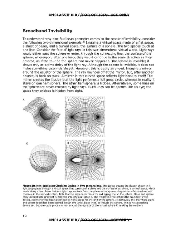
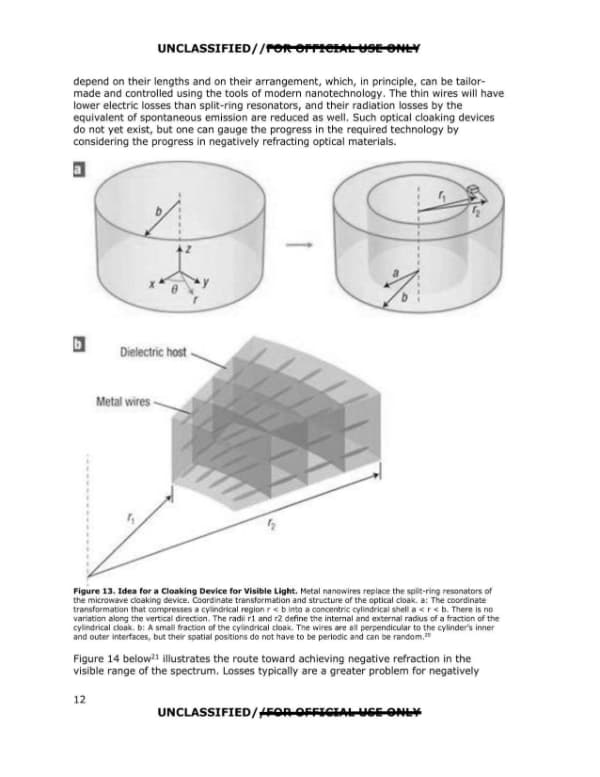
UNCLASSIFIED/ /FOR OFFICIAL USE ONLY Broadband Invisibility To understand why non-Euclidean geometry comes to the rescue of invisibility, consider the following two-dimensional example. 35 Imagine a virtual space made of a flat space, a sheet of paper, and a curved space, the surface of a sphere. The two spaces touch at one line. Consider the fate of light rays in this two-dimensional virtual world. Light rays would either pass the sphere or enter, through the connecting line, the surface of the sphere, whereupon, after one loop, they would continue in the same direction as they entered, as if the tour on the sphere had never happened. The sphere is invisible; it shows only as a time delay of the light ray. Although the sphere is invisible, it does not make something else invisible yet. However, this is easily arranged. Imagine a mirror around the equator of the sphere. The ray bounces off at the mirror, but, after another bounce, is back on track. A mirror in this curved space reflects light back to itself! The mirror creates the illusion that the light performs a full great circle, whereas in reality it stays on one hemisphere. The other hemisphere is hidden. Alternatively, some lines on the sphere are never crossed by light rays. Such lines can be opened like an eye; the space they enclose is hidden from sight. Figure 20. Non-Euclidean Cloaking Device in Two Dimensions. The device creates the illusion shown in A: light propagates through a virtual space that consists of a plane and the surface of a sphere, a curved space, which touch along a line. Some incident light rays venture from the plane to the sphere; they return after one loop and continue in the same direction. Note that the rays never cross the red zigzag line on the sphere. Plane and sphere carry a coordinate grid that is mapped onto physical space B. The magenta circle defines the boundary of the device. Its interior has been expanded to make space for the grid of the sphere. In particular, the line where plane and sphere touches has been opened like an eye (thick black lines) to include the sphere. This is not a cloaking device yet, but one could place a mirror around the equator of the virtual sphere C, making the northern 19 UNCLASSIFIED/ /FOR OFFICIAL USE ONLY