$DECLASSwnMfUvY5KfUN2LbKgyHXwmh39mGpJd7bjJw5A71pumpBuy
Declassified
Releases / Release 06 / DOW-UAP-D123
Department of War

AAWSAP DIRD, Positron Aerospace Propulsion, March 2010

This is a 2010 Defense Intelligence Reference Document on using positrons (antimatter) as a fuel for aerospace propulsion. It reviews concepts for UAVs, missiles, a single-stage launch vehicle and crewed Mars missions, and discusses positron production and storage. It concludes the concept is attractive in theory but depends on unsolved production and storage problems.

Record
DOW-UAP-D123
Release
Release 06 · Sep 18, 2026
Incident
2010-03-02 · Las Vegas, Nevada
Pages
35
Verdict
New
Source
war.gov ↗
Context · why this verdict

The overlap shows only matching cover and front-matter wording shared with other AAWSAP DIRDs in the same release (D121, D122); the technical body is not matched to any earlier release.

Findings in this document

4 findings

New SIG

Mars mission concept with positron engines and storage lifetime claims

  • Verbatim
    Missions must be established that can transport astronauts to Mars in less than 180 days.
    DOW-UAP-D123 · Release 06 · page 24 · war.gov ↗
  • Verbatim
    Proprietary experiments at Positronics Research LLC show that Ps atoms in crossed magnetic and electric fields in silica aerogel with 20-nm voids live up to 10 µs.
    DOW-UAP-D123 · Release 06 · page 32 · war.gov ↗

New or already public? No overlap with earlier releases.

New SIG

Report says positron-based EMP ordnance and longer BOMARC range are possible

  • Verbatim
    The BOMARC range could be increased to 2,000 km with 1 milligram (mg) of positrons.
    DOW-UAP-D123 · Release 06 · page 13 · war.gov ↗
  • Verbatim
    positrons could act as ordnance to destroy electronics on missiles or aircraft by electromagnetic pulse (EMP) by detonation of micrograms of positrons up to hundreds of meters from the target.18
    DOW-UAP-D123 · Release 06 · page 13 · war.gov ↗

New or already public? Not matched in the overlap.

New SIG

Single-stage vehicle concept: positron mass budget of 86.9 mg and 43% lower lift-off weight

  • Verbatim
    The positron mass budget for a 60,500-kg dry mass for ascension to LEO is 86.9 mg (Table 3).
    DOW-UAP-D123 · Release 06 · page 15 · war.gov ↗
  • Verbatim
    The GLOW of the positron SSRV is 43 percent less than that of the chemical SSRV owing to reduced propellant mass.
    DOW-UAP-D123 · Release 06 · page 14 · war.gov ↗
  • Context

    The vehicle is described as taking off horizontally from Edwards Air Force Base.

New or already public? Content is not in any matched earlier page.

New SIG

Report claims 150 µg of positrons could power a UAV around the Earth

  • Verbatim
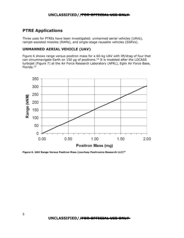
    Figure 6 shows range versus positron mass for a 60-kg UAV with lift/drag of four that can circumnavigate Earth on 150 µg of positrons.
    DOW-UAP-D123 · Release 06 · page 10 · war.gov ↗
  • Verbatim
    Within 10 years, the 150 µg of positrons required for a globe-encircling, nonstop turbojet flight could be made in 6 months at a cost of $69 million.
    DOW-UAP-D123 · Release 06 · page 32 · war.gov ↗
  • Context

    The catalogue description says the DIRD is a reference and synthesis product and that the concept remains highly speculative.

  • Inference · AI interpretation

    The cost figure appears as $96 million on page 29 per the page summary and $69 million on page 32, so the document's own numbers differ.

New or already public? No earlier release matches these pages in the overlap data.

Page by page

The pages and what the AI read on them

The transcription is the page reader's: black bars mark what the government redacted; hatched tags mark personal data we removed.

Page 1

Page 1 of 35

This is the cover page of Defense Intelligence Reference Document DIA-08-1003-002, titled Positron Aerospace Propulsion, dated 2 March 2010 with an ICOD of 1 December 2009. The page carries UNCLASSIFIED//FOR OFFICIAL USE ONLY markings at top and bottom.

UNCLASSIFIED//FOR OFFICIAL USE ONLY Defense Intelligence Reference Document Acquisition Threat Support 2 March 2010 ICOD: 1 December 2009 DIA-08-1003-002 Positron Aerospace Propulsion UNCLASSIFIED//FOR OFFICIAL USE ONLY
Page 2

Page 2 of 35 · 1 redaction

This is the front matter page of a Defense Intelligence Agency advanced technology report titled Positron Aerospace Propulsion, listing the preparing office, author, a copyright note, and contact instructions for questions about the document. The contact name is redacted.

UNCLASSIFIED//FOR OFFICIAL USE ONLY Positron Aerospace Propulsion Prepared by: Acquisition Support Division (DWO-3) Defense Warning Office Directorate for Analysis Defense Intelligence Agency Author: AAP Person 69 Administrative Note COPYRIGHT WARNING: Further dissemination of the photographs in this publication is not authorized. This product is one in a series of advanced technology reports produced in FY 2009 under the Defense Intelligence Agency, Defense Warning Office's Advanced Aerospace Weapon System Applications (AAWSA) Program. Comments or questions pertaining to this document should be addressed to [REDACTED], AAWSA Program Manager, Defense Intelligence Agency, ATTN: CLAR/DWO-3, Bldg 6000, Washington, DC 20340-5100. ii UNCLASSIFIED//FOR OFFICIAL USE ONLY
Page 3

Page 3 of 35

This is the table of contents page of a 2010 AAWSAP DIRD report on positron aerospace propulsion, listing sections and figures with page numbers. It is marked UNCLASSIFIED//FOR OFFICIAL USE ONLY, with the FOUO portion shown struck through in the header and footer.

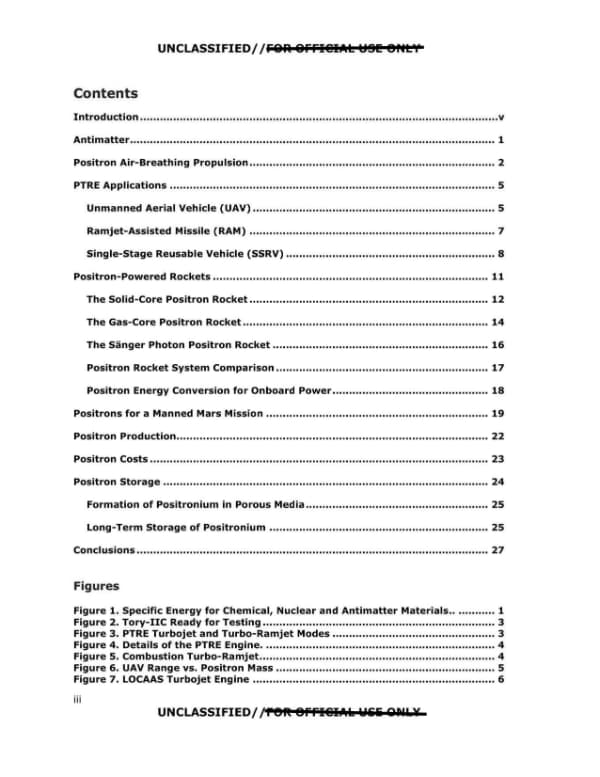
UNCLASSIFIED/ /FOR OFFICIAL USE ONLY Contents Introduction .......v Antimatter ....1 Positron Air-Breathing Propulsion ....2 PTRE Applications ....5 Unmanned Aerial Vehicle (UAV) ....5 Ramjet-Assisted Missile (RAM) ....7 Single-Stage Reusable Vehicle (SSRV) ....8 Positron-Powered Rockets ....11 The Solid-Core Positron Rocket ....12 The Gas-Core Positron Rocket ....14 The Sänger Photon Positron Rocket ....16 Positron Rocket System Comparison ....17 Positron Energy Conversion for Onboard Power ....18 Positrons for a Manned Mars Mission ....19 Positron Production ....22 Positron Costs ....23 Positron Storage ....24 Formation of Positronium in Porous Media ....25 Long-Term Storage of Positronium ....25 Conclusions ....27 Figures Figure 1. Specific Energy for Chemical, Nuclear and Antimatter Materials.. ....1 Figure 2. Tory-IIC Ready for Testing ....3 Figure 3. PTRE Turbojet and Turbo-Ramjet Modes ....3 Figure 4. Details of the PTRE Engine. ....4 Figure 5. Combustion Turbo-Ramjet....4 Figure 6. UAV Range vs. Positron Mass ....5 Figure 7. LOCAAS Turbojet Engine ....6 iii UNCLASSIFIED/ /FOR OFFICIAL USE ONLY
Page 4

Page 4 of 35

This is the front-matter list of figures and tables (page iv) of a positron aerospace propulsion report, listing figure and table titles with page numbers. The page is marked UNCLASSIFIED / FOR OFFICIAL USE ONLY and contains no redactions.

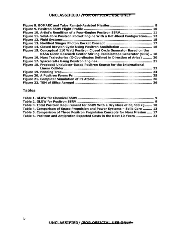
UNCLASSIFIED/ J FOR OFFICIAL USE ONLY Figure 8. BOMARC and Talos Ramjet-Assisted Missiles........................................... 8 Figure 15. Conceptual 110 Watt Positron Closed Cycle Generator Based on the Figure 18. Proposed Undulator-Based Positron Source for the International Figure 9. Positron SSRV Flight Profile .................................................................. 10 Figure 10. Artist's Rendition of a Four-Engine Positron SSRV............................... 11 Figure 11. Solid-Core Positron Rocket Engine With a Hot-Bleed Configuration..... 12 Figure 12. Fluid Systems ...................................................................................... 15 Figure 13. Modified Sanger Photon Rocket Concept ............................................. 17 Figure 14. Closed Brayton Cycle Using Positron Annihilation ............................... 18 NASA Glenn Research Center Stirling Radioisotope Generator (SRG) .. 18 Figure 16. Mars Trajectories (X-Coordinates Defined in Direction of Aries) ......... 20 Figure 17. Spacecrafts Using Positron Engines..................................................... 21 Linear Collider ..................................................................................... 22 Figure 19. Penning Trap ....................................................................................... 24 Figure 20. A Positron Forms Ps ............................................................................ 25 Figure 21. Computer Simulation of Ps Atoms ....................................................... 26 Figure 22. TEM of Silica Aerogel ........................................................................... 26 Tables Table 1. GLOW for Chemical SSRV .......................................................................... 9 Table 2. GLOW for Positron SSRV ........................................................................... 9 Table 3. Total Positron Requirement for SSRV With a Dry Mass of 60,500 kg ....... 10 Table 4. Comparison of Space Propulsion and Power Systems - Solid Core ......... 13 Table 5. Comparison of Three Positron Propulsion Concepts for Mars Mission ..... 17 Table 6. Positron and Antiproton Expected Costs in the Next 10 Years ................ 23 UNCLASSIFIED/ /FAR OEEJCI0la fliE QPI .. ¥ iv UNCLASSIFIED/ /FOR OFFICIAL USE ONLY Figure 8. BOMARC and Talos Ramjet-Assisted Missiles........................................... 8 Figure 9. Positron SSRV Flight Profile .................................................................. 10 Figure 10. Artist's Rendition of a Four-Engine Positron SSRV............................... 11 Figure 11. Solid-Core Positron Rocket Engine With a Hot-Bleed Configuration..... 12 Figure 12. Fluid Systems ...................................................................................... 15 Figure 13. Modified Sänger Photon Rocket Concept ............................................. 17 Figure 14. Closed Brayton Cycle Using Positron Annihilation ............................... 18 Figure 15. Conceptual 110 Watt Positron Closed Cycle Generator Based on the NASA Glenn Research Center Stirling Radioisotope Generator (SRG) .. 18 Figure 16. Mars Trajectories (X-Coordinates Defined in Direction of Aries) ......... 20 Figure 17. Spacecrafts Using Positron Engines..................................................... 21 Figure 18. Proposed Undulator-Based Positron Source for the International Linear Collider ..................................................................................... 22 Figure 19. Penning Trap ....................................................................................... 24 Figure 20. A Positron Forms Ps ............................................................................ 25 Figure 21. Computer Simulation of Ps Atoms ....................................................... 26 Figure 22. TEM of Silica Aerogel ........................................................................... 26 Tables Table 1. GLOW for Chemical SSRV .......................................................................... 9 Table 2. GLOW for Positron SSRV ........................................................................... 9 Table 3. Total Positron Requirement for SSRV With a Dry Mass of 60,500 kg ....... 10 Table 4. Comparison of Space Propulsion and Power Systems – Solid Core ......... 13 Table 5. Comparison of Three Positron Propulsion Concepts for Mars Mission ..... 17 Table 6. Positron and Antiproton Expected Costs in the Next 10 Years ................ 23 iv UNCLASSIFIED/ /FOR OFFICIAL USE ONLY
Page 5

Page 5 of 35

This is the introduction page of a 2010 paper titled 'Positron Aerospace Propulsion,' describing antimatter as an aerospace fuel and summarizing the paper's scope and sponsors. The page includes a classification header with garbled markings and a page marker 'V'.

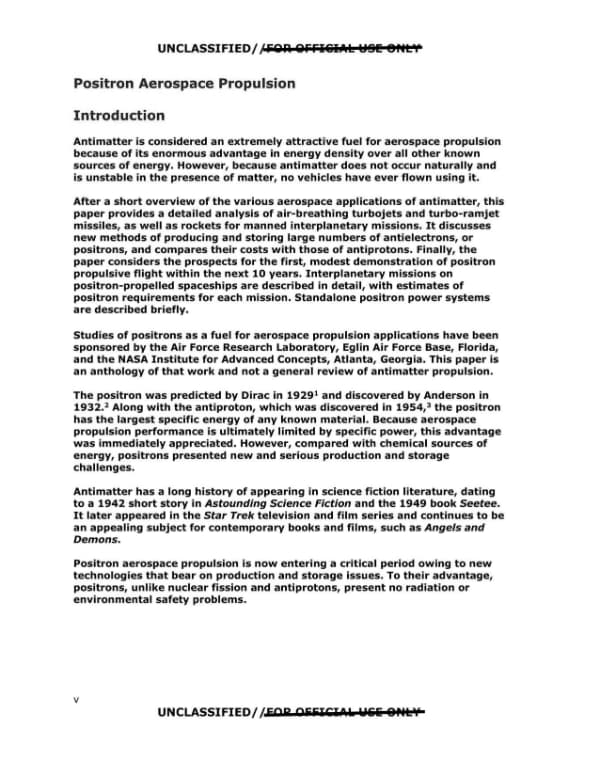
UNCLASSIFIED/fFOA 8FFl&IAl l48l: 8HL'I Positron Aerospace Propulsion Introduction Antimatter is considered an extremely attractive fuel for aerospace propulsion because of its enormous advantage in energy density over all other known sources of energy. However, because antimatter does not occur naturally and is unstable in the presence of matter, no vehicles have ever flown using it. After a short overview of the various aerospace applications of antimatter, this paper provides a detailed analysis of air-breathing turbojets and turbo-ramjet missiles, as well as rockets for manned interplanetary missions. It discusses new methods of producing and storing large numbers of antielectrons, or positrons, and compares their costs with those of antiprotons. Finally, the paper considers the prospects for the first, modest demonstration of positron propulsive flight within the next 10 years. Interplanetary missions on positron-propelled spaceships are described in detail, with estimates of positron requirements for each mission. Standalone positron power systems are described briefly. Studies of positrons as a fuel for aerospace propulsion applications have been sponsored by the Air Force Research Laboratory, Eglin Air Force Base, Florida, and the NASA Institute for Advanced Concepts, Atlanta, Georgia. This paper is an anthology of that work and not a general review of antimatter propulsion. The positron was predicted by Dirac in 19291 and discovered by Anderson in 1932.2 Along with the antiproton, which was discovered in 1954,3 the positron has the largest specific energy of any known material. Because aerospace propulsion performance is ultimately limited by specific power, this advantage was immediately appreciated. However, compared with chemical sources of energy, positrons presented new and serious production and storage challenges. Antimatter has a long history of appearing in science fiction literature, dating to a 1942 short story in Astounding Science Fiction and the 1949 book Seetee. It later appeared in the Star Trek television and film series and continues to be an appealing subject for contemporary books and films, such as Angels and Demons. Positron aerospace propulsion is now entering a critical period owing to new technologies that bear on production and storage issues. To their advantage, positrons, unlike nuclear fission and antiprotons, present no radiation or environmental safety problems. UNCLASSIFIED/ /FAR AEEICllk Wlili 8Nl¥ V
Page 6

Page 6 of 35

This page is the first page of a section titled 'Antimatter' from an unclassified but FOR OFFICIAL USE ONLY report, describing antimatter properties, positronium annihilation, and its energy density compared with chemical, fission and fusion sources, with a bar chart in Figure 1. The page contains no redactions.

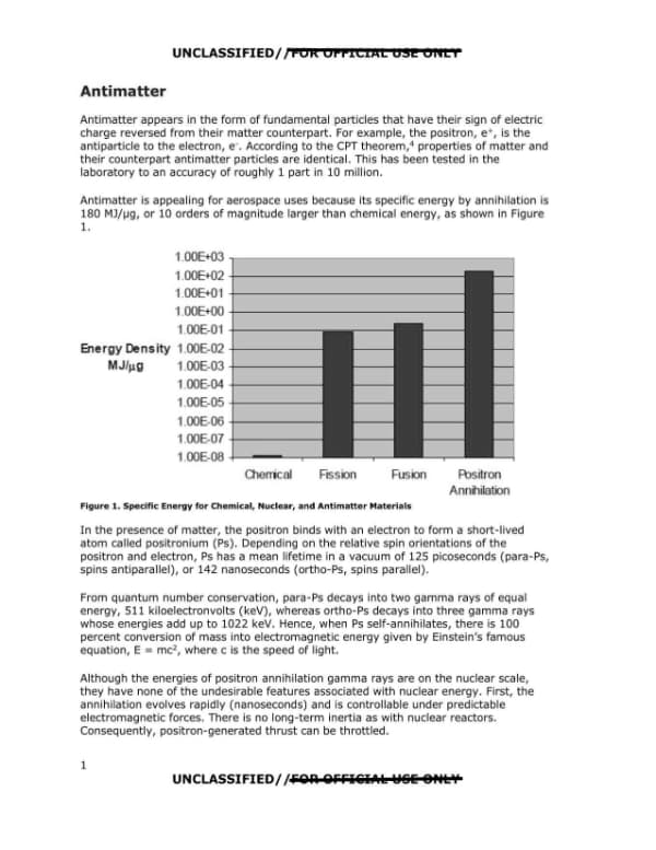
UNCLASSIFIED/ JFOR OFFICIAL USE 014[ I Antimatter Antimatter appears in the form of fundamental particles that have their sign of electric charge reversed from their matter counterpart. For example, the positron, e+, is the antiparticle to the electron, e·. According to the CPT theorem, 4 properties of matter and their counterpart antimatter particles are identical. This has been tested in the laboratory to an accuracy of roughly 1 part in 10 million. Antimatter is appealing for aerospace uses because its specific energy by annihilation is 180 MJ/µg, or 10 orders of magnitude larger than chemical energy, as shown in Figure 1. 1.00E+03 ~--------------- 1.00E+02 +-------------- 1.00E+01 +-------------- 1.00E+O0 -+-------------- 1.00E-01 -+------ Energy Density _OOE-02 ----- MJ/µg 1.00E-03 ----- _OOE-04 +------- 1.00E-05 +------ 1.00E-06 -+------ 1.00E-07 -+------ 1.00E-08 -1-----.,---- Olerrical Fission Fusion Fbsitron Annihilation Figure 1. Specific Energy for Chemical, Nuclear, and Antimatter Materials In the presence of matter, the positron binds with an electron to form a short-lived atom called positronium (Ps). Depending on the relative spin orientations of the positron and electron, Ps has a mean lifetime in a vacuum of 125 picoseconds (para-Ps, spins antiparallel), or 142 nanoseconds (ortho-Ps, spins parallel). From quantum number conservation, para-Ps decays into two gamma rays of equal energy, 511 kiloelectronvolts (keV), whereas ortho-Ps decays into three gamma rays whose energies add up to 1022 keV. Hence, when Ps self-annihilates, there is 100 percent conversion of mass into electromagnetic energy given by Einstein's famous equation, E = mc2, where c is the speed of light. Although the energies of positron annihilation gamma rays are on the nuclear scale, they have none of the undesirable features associated with nuclear energy. First, the annihilation evolves rapidly (nanoseconds) and is controllable under predictable electromagnetic forces. There is no long-term inertia as with nuclear reactors. Consequently, positron-generated thrust can be throttled. UNCLASSIFIED/ /570A OFFl&IAk W&E 8HLY 1
Page 7

Page 7 of 35

Page 2 of a report on positron aerospace propulsion, comparing positron annihilation with antiproton annihilation, discussing obstacles to positron use, and summarizing early US nuclear aircraft and nuclear ramjet programs. The page is numbered 2 and bears UNCLASSIFIED//FOR OFFICIAL USE ONLY markings.

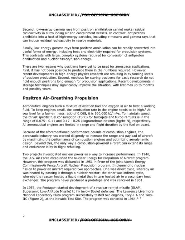
UNCLASSIFIED/ /FOR OFFICIAL USE ONLY Second, low-energy gamma rays from positron annihilation cannot make residual radioactivity in surrounding air and containment vessels. In contrast, antiprotons annihilate into a host of high-energy particles, including π-mesons and gamma rays that can induce residual radioactivity in nearby materials. Finally, low-energy gamma rays from positron annihilation can be readily converted into useful forms of energy, including heat and electricity required for propulsion systems. This contrasts with large, complex systems required for conversion of antiproton annihilation and nuclear fission/fusion energy. There are two reasons why positrons have yet to be used for aerospace applications. First, it has not been possible to produce them in the numbers required. However, recent developments in high-energy physics research are resulting in expanding levels of positron production. Second, methods for storing positrons for basic research do not hold enough positrons long enough for propulsion applications. Recent developments in storage techniques may significantly improve the situation, with lifetimes up to months and possibly years. Positron Air-Breathing Propulsion Aeronautical engines burn a mixture of aviation fuel and oxygen in air to heat a working fluid. To keep engines small, the combustion rate in the engine needs to be high.5 At sea level for a fuel-air mass ratio of 0.068, it is 500,000 kJ/m3-s. To maintain speed, the thrust specific fuel consumption (TSFC) for turbojets and turbo-ramjets is in the range of 0.075 - 0.11 and 0.17 - 0.26 kilogram/hour-Newton (kg/hr-N), respectively. All aeronautical engines are limited in range and flight duration by the fuel on board. Because of the aforementioned performance bounds of combustion engines, the aeronautic industry has worked diligently to increase the range and payload of aircraft by maximizing the performance of combustion engines and optimizing aerodynamic design. Beyond this, the only way a combustion-powered aircraft can extend its range and endurance is by in-flight refueling. Two projects investigated nuclear power as a way to increase performance. In 1946, the U.S. Air Force established the Nuclear Energy for Propulsion of Aircraft program. However, this program was disbanded in 1951 in favor of the joint Atomic Energy Commission-Air Force Aircraft Nuclear Propulsion program. Implementing nuclear fission to power an aircraft required two approaches. One was direct cycle, whereby air was heated by passing it through a nuclear reactor; the other was indirect cycle, whereby the reactor heated a liquid metal that in turn heated air in a secondary heat exchanger. The program never produced a prototype and was canceled in 1961. In 1957, the Pentagon started development of a nuclear ramjet missile (SLAM, Supersonic Low-Altitude Missile) to fly below Soviet defenses. The Lawrence Livermore National Laboratory Pluto program successfully tested two engines, Tory-IIA and Tory-IIC (Figure 2), at the Nevada Test Site. The program was canceled in 1964.6, 7 2 UNCLASSIFIED/ /FOR OFFICIAL USE ONLY
Page 8

Page 8 of 35

Page 3 of a document on positron propulsion containing two figures: a photograph of the Tory-IIC ready for testing and a labeled diagram of a positron turbojet/ramjet engine (PTRE). The accompanying text states that tungsten shells are heated by gamma rays, with heat transferred to air by convection.

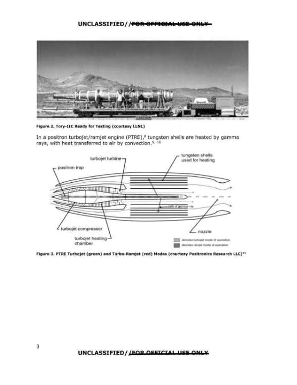
UNCLASSIFIED/ /FOR OFFICIAL USE ONLY Figure 2. Tory-IIC Ready for Testing (courtesy LLNL) In a positron turbojet/ramjet engine (PTRE),8 tungsten shells are heated by gamma rays, with heat transferred to air by convection.9, 10 turbojet turbine | tungsten shells used for heating positron trap turbojet compressor turbojet heating chamber nozzle path of gamma ray denotes turbojet mode of operation denotes ramjet mode of operation Figure 3. PTRE Turbojet (green) and Turbo-Ramjet (red) Modes (courtesy Positronics Research LLC)11 3 UNCLASSIFIED/ /FOR OFFICIAL USE ONLY
Page 9

Page 9 of 35

This page presents two engine cutaway diagrams, Figure 4 (the PTRE engine) and Figure 5 (a combustion turbo-ramjet), with brief captions and one sentence comparing heating methods. The diagrams are credited to Positronics Research LLC.

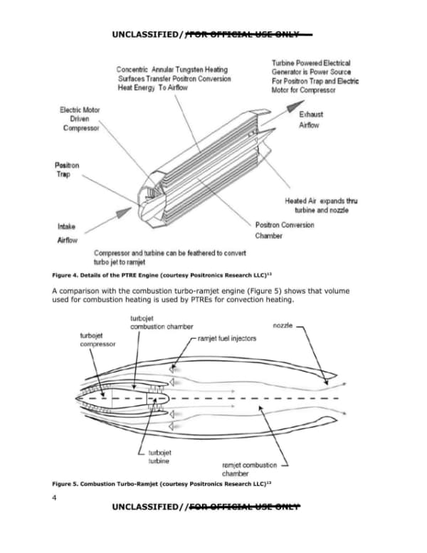
UNCLASSIFIED//re1t OFFl@IAL Y§li 8Ptllf Tur ·n Pow r dElectric I Co nn I r Tungst n H g G r Pow Sourc Air w Comp, sor nd turb n can be t ath red to conv rt urbo j Ito r m I Figure 4. Details of the PTRE Engine {courtesy Positronics Research LLC} 12 A comparison with the combustion turbo-ramjet engine (Figure 5) shows t hat volume used for combustion heating is used by PTREs for convection heating. El tr c Motor Dr' n ompr sor Po i on Tr Int Surf nsf Conv r ion Tra n 8 tr c H To 01) H d r xp nds ru rbin nd no P • r on Conv rs n Chm , turbojet or tur ojet combustion chamber turbojet ramjet fuel Injectors ramJet combus on turbine chamber Figure 5. Combustion Turbo-Ramjet (courtesy Positronics Research LLC) 13 UNCLASSIFIED/ /FOA 8FFI€iIAL YSIE er•t'I" 4 [DIAGRAM: Engine cutaway labelled Concentric Annular Tungsten Heating Surfaces Transfer Positron Conversion Heat Energy To Airflow; Turbine Powered Electrical Generator is Power Source For Positron Trap and Electric Motor for Compressor; Electric Motor Driven Compressor; Positron Trap; Intake Airflow; Exhaust Airflow; Heated Air expands thru turbine and nozzle; Positron Conversion Chamber; Compressor and turbine can be feathered to convert turbo jet to ramjet] [DIAGRAM: Combustion turbo-ramjet cutaway labelled turbojet compressor, turbojet combustion chamber, ramjet fuel injectors, nozzle, turbojet turbine, ramjet combustion chamber] UNCLASSIFIED/ /FOR OFFICIAL USE ONLY
Page 10

Page 10 of 35 · 2 redactions

Page 5 of the PTRE applications section describes a figure of UAV range versus positron mass for a 60-kg UAV modeled after the LOCASS turbojet at AFRL, Eglin Air Force Base. The page is headed with unclassified markings, and the header and footer contain obscured FOUO text.

UNCLASSIFIED//re1t Offl@IAL lel§li 8PUs:lf PTRE Applications Three uses for PTREs have been investigated: unmanned aerial vehicles (UAVs), ramjet-assisted missiles (RAMs), and single-stage reusable vehicles (SSRVs). UNMANNED AERIAL VEHICLE {UAV) Figure 6 shows range versus positron mass for a 60-kg UAV with lift/drag of four that can circumnavigate Earth on 150 µg of positrons. 14 It is modeled after the LOCASS turbojet (Figure 7) at the Air Force Research Laboratory (AFRL), Eglin Air Force Base, Florida .15 350 300 - 250 ~ z .::it:. 200 -a, O'I 150 s:: C,:J Ct: 100 50 0 0.00 0.50 1.00 1.50 2.00 Positron Mass (mg) Figure 6. UAV Range Versus Positron Mass (courtesy Positronics Research LLC) 16 UNCLASSIFIED/ ,'FOR. OFFl&IAls: lel&li 8Ptls:lf 5 UNCLASSIFIED/ [REDACTED] PTRE Applications Three uses for PTREs have been investigated: unmanned aerial vehicles (UAVs), ramjet-assisted missiles (RAMs), and single-stage reusable vehicles (SSRVs). UNMANNED AERIAL VEHICLE (UAV) Figure 6 shows range versus positron mass for a 60-kg UAV with lift/drag of four that can circumnavigate Earth on 150 µg of positrons.14 It is modeled after the LOCASS turbojet (Figure 7) at the Air Force Research Laboratory (AFRL), Eglin Air Force Base, Florida.15 [Chart: Range (kNM) versus Positron Mass (mg), x-axis 0.00 to 2.00, y-axis 0 to 350; line rising from 0 at 0.00 mg to roughly 300 kNM at 2.00 mg; approximately 150 kNM at 1.00 mg] Figure 6. UAV Range Versus Positron Mass (courtesy Positronics Research LLC)16 5 UNCLASSIFIED/ [REDACTED]
Page 11

Page 11 of 35

A page showing a photograph of a LOCAAS turbojet engine UAV airframe with a figure caption, followed by a bulleted list of claimed dual-use applications for a positron-fueled UAV, divided into military and civil/state/local categories. The page is numbered 6 at the bottom.

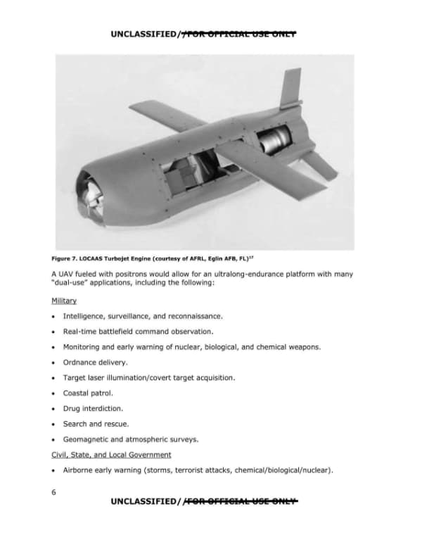
UNCLASSIFIED//FOR OFFICIAL USE ONLY Figure 7. LOCAAS Turbojet Engine (courtesy of AFRL, Eglin AFB, FL) 17 A UAV fueled with positrons would allow for an ultralong-endurance platform with many "dual-use" applications, including the following: Military • Intelligence, surveillance, and reconnaissance. • Real-time battlefield command observation. • Monitoring and early warning of nuclear, biological, and chemical weapons. • Ordnance delivery. • Target laser illumination/covert target acquisition. • Coastal patrol. • Drug interdiction. • Search and rescue. • Geomagnetic and atmospheric surveys. Civil, State, and Local Government • Airborne early warning (storms, terrorist attacks, chemical/biological/nuclear). 6 UNCLASSIFIED//FOR OFFICIAL USE ONLY
Page 12

Page 12 of 35

A page from a 2010 AAWSAP DIRD Positron Aerospace Propulsion report listing civil and commercial monitoring applications and airline advantages, followed by a short section on the ramjet-assisted missile (RAM) and the BOMARC and Talos/Vandal missiles. The page is marked UNCLASSIFIED//FOR OFFICIAL USE ONLY.

UNCLASSIFIED/ /FOR OFFICIAL USE ONLY • Environmental/pollution monitoring. • Fire detection and monitoring. • Aerial surveying. • Weather and atmospheric monitoring. • Border patrol. • Emergency communications relay. • Drug interdiction. • Law enforcement. • Highway/road monitoring. • Search and rescue. Commercial • Iceberg patrol/tracking in shipping lanes. • Railway/pipeline/power line monitoring. • Commercial fishing reconnaissance/sea-life monitoring. • Environmental/pollution monitoring. • Livestock monitoring. • Mineral exploration. • Weather sensing. • Agriculture. Additional advantages to the commercial airline industry: • Less propellant means increased payload/passenger per aircraft. • Global nonstop flights are possible. • Increase in structural mass allows more electronics/passenger amenities. RAMJET-ASSISTED MISSILE (RAM) The BOMARC 440-kilometer (km)-range antiaircraft missile was developed by the U.S. Air Force in the 1950s to counter Soviet bombers. In the 1960s, the Talas, a long-range surface-to-air missile, was developed by the U.S. Navy and later converted to the Vandal missile. Both ramjets (Figure 8) activated at mach 1. 7 UNCLASSIFIED/ /FOR OFFICIAL USE ONLY