$DECLASSwnMfUvY5KfUN2LbKgyHXwmh39mGpJd7bjJw5A71pumpBuy
Declassified
Releases / Release 06 / DOW-UAP-D121
Department of War

AAWSAP DIRD, Pulsed High-Power Microwave Source Technology, January 2010

This document is a Defense Intelligence Reference Document (DIRD), a technical reference format used by the Defense Intelligence Agency (DIA) to capture baseline knowledge on a specific topic for later analytic use. DIRDs are best understood as reference and synthesis products rather than as original research. It is one of 38 DIRDs produced under the Advanced Aerospace Weapon System Applications Program (AAWSAP) between 2009 and 2011. Because AAWSAP’s scope permitted a broad range of supporting topics, not every DIRD in the series directly concerns aerospace systems or future threat assessment. The following summary reflects the DIRD’s scope and framing at the time of writing and should…

Catalogue description by the publishing agency.

Record
DOW-UAP-D121
Release
Release 06 · Sep 18, 2026
Incident
2010-01-28 · Las Vegas, Nevada
Pages
37
Verdict
not judged yet
Source
war.gov ↗
Page by page

The pages and what the AI read on them

The transcription is the page reader's: black bars mark what the government redacted; hatched tags mark personal data we removed.
Page 1

Page 1 of 37

This is the cover page of a Defense Intelligence Reference Document titled "Pulsed High-Power Microwave Source Technology", dated 28 January 2010 with ICOD 1 December 2009 and document number DIA-08-0912-005. The page is marked UNCLASSIFIED//FOR OFFICIAL USE ONLY and bears a DIA seal.
UNCLASSIFIED//FOR OFFICIAL USE ONLY Defense Intelligence Reference Document Acquisition Threat Support 28 January 2010 ICOD: 1 December 2009 DIA-08-0912-005 Pulsed High-Power Microwave Source Technology UNCLASSIFIED//FOR OFFICIAL USE ONLY
Page 2

Page 2 of 37 · 1 redaction

This is the front matter page of a Defense Intelligence Agency advanced technology report on pulsed high-power microwave source technology, prepared by the Acquisition Support Division under the AAWSA Program. It contains an administrative note, a copyright warning, and contact instructions for the AAWSA Program Manager, whose name is redacted.
UNCLASSIFIED//FOR OFFICIAL USE ONLY Pulsed High-Power Microwave Source Technology Prepared by: Acquisition Support Division (DWO-3) Defense Warning Office Directorate for Analysis Defense Intelligence Agency Author: AAP Person 64 Administrative Note COPYRIGHT WARNING: Further dissemination of the photographs in this publication is not authorized. This product is one in a series of advanced technology reports produced in FY 2009 under the Defense Intelligence Agency, Defense Warning Office's Advanced Aerospace Weapon System Applications (AAWSA) Program. Comments or questions pertaining to this document should be addressed to [REDACTED] AAWSA Program Manager, Defense Intelligence Agency, ATTN: CLAR/DWO-3, Bldg 6000, Washington, DC 20340-5100. ii UNCLASSIFIED//FOR OFFICIAL USE ONLY
Page 3

Page 3 of 37

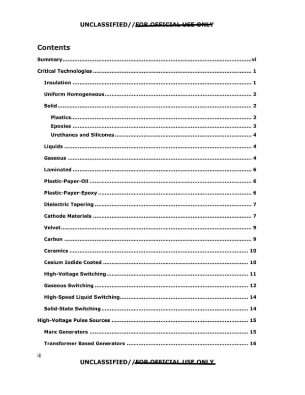
This is the table of contents page of a document, listing section titles and page numbers from Summary through Transformer Based Generators. It bears UNCLASSIFIED//FOR OFFICIAL USE ONLY markings at top and bottom, with the 'FOR OFFICIAL USE ONLY' portion struck through.
UNCLASSIFIED//FOR OFFICIAL USE ONLY Contents Summary................................................................................................................vi Critical Technologies .............................................................................................. 1 Insulation .......................................................................................................... 1 Uniform Homogeneous ....................................................................................... 2 Solid ................................................................................................................... 2 Plastics............................................................................................................ 2 Epoxies ................ ,..............................., .......................................................... 3 Urethanes and Silicones ................................................................................. 4 Liquids ............................................................................................................... 4 Gaseous .............................................................................................................. 4 Laminated .......................................................................................................... 6 Plastic-Paper-Oil ................................................................................................ 6 Plastic-Paper-Epoxy ........................................................................................... 6 Dielectric Tapering ............................................................................................. 7 Cathode Materials .............................................................................................. 7 Velvet................................................................................................................. 9 Carbon ............................................................................................................... 9 Ceramics .......................................................................................................... 10 Cesium Iodide Coated ...................................................................................... 10 High-Voltage Switching .................................................................................... 11 Gaseous Switching ........................................................................................... 12 High-Speed Liquid Switching............................................................................ 14 Solid-State Switching ....................................................................................... 14 High-Voltage Pulse Sources ................................................................................. 15 Marx Generators .............................................................................................. 15 Transformer Based Generators ........................................................................ 16 iii UNCLASSIFIED//FOR OFFICIAL USE ONLY
Page 4

Page 4 of 37

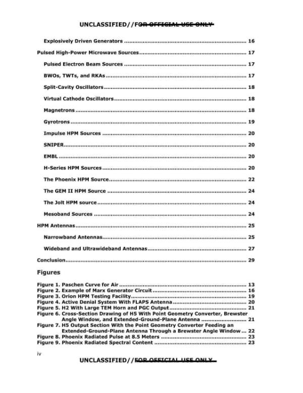
This is page iv of a report's table of contents and list of figures, listing section headings and page numbers for Explosively Driven Generators through Conclusion and Figures 1 through 9. The page is marked UNCLASSIFIED//FOR OFFICIAL USE ONLY with a strikethrough on part of the marking.
UNCLASSIFIED/ /rtiUl 9FFl&IAl W&li 8,.lV Explosively Driven Generators ......................................................................... 16 Pulsed High-Power Microwave Sources ................................................................ 17 Pulsed Electron Beam Sources ......................................................................... 17 BWOs, TWTs, and RKAs ..................................................................................... 17 Split-Cavity Oscillators ..................................................................................... 18 Virtual Cathode Oscillators ............................................................................... 18 Magnetrons ...................................................................................................... 18 Gyrotrons ......................................................................................................... 19 Impulse HPM Sources ...................................................................................... 20 SNIPER............................................................................................................. 20 EMBL ................................................................................................................ 20 H-Series HPM Sources ...................................................................................... 20 The Phoenix HPM Source.................................................................................. 22 The GEM II HPM Source ................................................................................... 24 The Jolt HPM source ......................................................................................... 24 Mesoband Sources ........................................................................................... 24 HPM Antennas ...................................................................................................... 25 Narrowband Antennas...................................................................................... 25 Wideband and Ultrawideband Antennas ........................................................... 27 Conclusion ............................................................................................................ 29 Figures Figure 1. Paschen Curve for Air ............................................................................ 13 Figure 6. Cross-Section Drawing of HS With Point Geometry Converter, Brewster Figure 7. HS Output Section With the Point Geometry Converter Feeding an Figure 2. Example of Marx Generator Circuit ........................................................ 16 Figure 3. Orion HPM Testing Facility....................................................................... 19 Figure 4. Active Denial System With FLAPS Antenna ............................................ 20 Figure 5. H2 With Large TEM Horn and PGC Output .............................................. 21 Angle Window, and Extended-Ground-Plane Antenna ........................... 21 Extended-Ground-Plane Antenna Through a Brewster Angle Window ... 22 Figure 8. Phoenix Radiated Pulse at 8.5 Meters ................................................... 23 Figure 9. Phoenix Radiated Spectral Content ....................................................... 23 UNCLASSIFIED/ /fiAR AEEJCJOP 11 55 ON! X iv UNCLASSIFIED//FOR OFFICIAL USE ONLY Explosively Driven Generators ......................................................................... 16 Pulsed High-Power Microwave Sources ................................................................ 17 Pulsed Electron Beam Sources ......................................................................... 17 BWOs, TWTs, and RKAs ..................................................................................... 17 Split-Cavity Oscillators ..................................................................................... 18 Virtual Cathode Oscillators ............................................................................... 18 Magnetrons ...................................................................................................... 18 Gyrotrons ......................................................................................................... 19 Impulse HPM Sources ...................................................................................... 20 SNIPER............................................................................................................. 20 EMBL ................................................................................................................ 20 H-Series HPM Sources ...................................................................................... 20 The Phoenix HPM Source.................................................................................. 22 The GEM II HPM Source ................................................................................... 24 The Jolt HPM source ......................................................................................... 24 Mesoband Sources ........................................................................................... 24 HPM Antennas ...................................................................................................... 25 Narrowband Antennas...................................................................................... 25 Wideband and Ultrawideband Antennas ........................................................... 27 Conclusion ............................................................................................................ 29 Figures Figure 1. Paschen Curve for Air ............................................................................ 13 Figure 2. Example of Marx Generator Circuit ........................................................ 16 Figure 3. Orion HPM Testing Facility....................................................................... 19 Figure 4. Active Denial System With FLAPS Antenna ............................................ 20 Figure 5. H2 With Large TEM Horn and PGC Output .............................................. 21 Figure 6. Cross-Section Drawing of H5 With Point Geometry Converter, Brewster Angle Window, and Extended-Ground-Plane Antenna ........................... 21 Figure 7. H5 Output Section With the Point Geometry Converter Feeding an Extended-Ground-Plane Antenna Through a Brewster Angle Window ... 22 Figure 8. Phoenix Radiated Pulse at 8.5 Meters ................................................... 23 Figure 9. Phoenix Radiated Spectral Content ....................................................... 23 iv UNCLASSIFIED//FOR OFFICIAL USE ONLY
Page 5

Page 5 of 37

This page is the list of figures and tables from the front matter of a Pulsed High-Power Microwave Source Technology report, marked UNCLASSIFIED//FOR OFFICIAL USE ONLY. It lists figure and table titles with their page numbers.
UNCLASSIFIED//FOR OFFICIAL USE ONLY Figure 10. Jolt Hyperband HPM Source................................................................. 24 Figure 11. Jolt Radiated Electric Field Waveform at 85 Meters ............................. 24 Figure 12. FLAPS Antenna With a Cross-Shorted Dipole Array ............................. 26 Figure 13. Mode Converter Vlasov Antenna and Vlasov Antenna Attached to a Coaxial MILO ....................................................................................... 27 Tables Table 1. Dielectric Properties of Some HPM Plastics ............................................... 3 Table 2. Relative Spark Breakdown Strength of Gases ........................................... S Table 3. Cathode Study Findings .......................................................................... 11 UNCLASSIFIED//FOR OFFICIAL USE ONLY V UNCLASSIFIED//FOR OFFICIAL USE ONLY
Page 6

Page 6 of 37

This is the summary page of a paper overviewing pulsed high-power microwave source technology, describing HEMP origins, the 1962 Starfish Prime test, and the emergence of HPM weapons. The page is marked UNCLASSIFIED//FOR OFFICIAL USE ONLY and is numbered vi.
UNCLASSIFIED//FOR OFFICIAL USE ONLY Pulsed High-Power Microwave Source Technology Summary This paper provides an overview of the major types of high-power microwave (HPM) sources and the critical technologies required to build them. Pulsed HPM technology has been of scientific and military interest for several decades. Originally, the interest focused on the area of high-altitude electromagnetic pulse (HEMP) concerns. HEMP is produced when a nuclear weapon is detonated high above the earth's surface, creating gamma radiation that interacts with the atmosphere to create an intense electromagnetic (EM) energy field that is harmless to people as it radiates outward but can overload computer circuitry with effects similar to, but causing damage more swiftly than, a lightning strike. HEMP effects became fully known in 1962, when a high-altitude nuclear test (codenamed "Starfish Prime") over the Pacific Ocean disrupted radio stations and electronic equipment 800 miles away in Hawaii. The HEMP effect can span thousands of miles, depending on the altitude, design, and power of the nuclear burst. It is speculated that a single device detonated at high altitude over the central United States could affect the entire country, since the HEMP would be picked up by conductors, such as wires and power cables, acting as antennas to conduct the electrical energy into various electronic systems. This EM radiation was found to have field levels on the order of several hundreds of kilovolts per meter with onset or rise times of a few nanoseconds and a duration of nearly a microsecond. Fields of these magnitudes were found to have severe detrimental effects on numerous electrical systems and items, such as the power grid, automobiles, communications equipment, and aircraft. Much testing was done in the 1960s and 1970s to determine vulnerabilities and to find mitigation solutions. The HEMP is essentially a wideband microwave pulse, and several EMP simulators were devised and built for use in testing its effect on various electronic systems. In addition, several programs were established to investigate the possibility of generating and radiating other spectrums of EM radiation that may have some of these same effects without requiring a nuclear detonation. This was the impetus for the advancement of pulsed HPM technologies for weapons. HPM radiation is composed of shorter waveforms at higher frequencies than is HEMP, which makes it highly effective against electronic equipment and more difficult to harden against. Whereas HEMP weapons are large in scale and require a nuclear capability along with technology to launch high-altitude missiles, HPM weapons are smaller in scale, involve a much lower level of technology, and are within the capability of almost any state. HPMs can damage computers and electronics similar to the way HEMP can, although the effects are limited to a much shorter range. Technical accessibility, lower cost, and the vulnerability of U.S. electronic equipment could make small-scale HPM weapons attractive to terrorist groups. HPM devices are now categorized as directed-energy weapons. vi UNCLASSIFIED//FOR OFFICIAL USE ONLY
Page 7

Page 7 of 37

Page vii of a US government report on pulsed high-power microwave (HPM) source technology, discussing HPM use for electronic attack and how semiconductor damage thresholds scale with pulse duration. The page states that a U.S. Commanche helicopter performing HPM tests in New York state on 28 May 2001 was reported to have generated a pulse that disrupted GPS devices used to land aircraft in Albany.
UNCLASSIFIED//FOR OFFICIAL USE ONLY One major use of HPM by the military is for electronic attack, or what is referred to by the media as an "ebomb." HPM sources developed for this purpose provide peak powers in excess of 10 gigawatts. The goal of such a weapon is to disable communications and computer systems prior to any troop movements and render the enemy unable to stage a response. The technology used to drive such sources has its roots in pulsed power, and for narrowband sources requires the use of tools that have been developed in the plasma physics community. Reliance on microprocessors that have an increasing density of circuits packaged onto each chip makes such systems ever-more vulnerable to HPM effects. As an example of the possible effects of HPM weapons, on 28 May 2001, a U.S. Commanche helicopter, flying in New York state while performing tests involving HPM weapons, was reported to have generated a low-level energy pulse that disrupted the Global Positioning System devices used to land commercial aircraft in Albany. The use of this type of weapon can be based on several scenarios, depending on the asset it will be used against. Sometimes, it may only be necessary to upset a data bus transfer to produce a success; other times, success may not be so simple. Some of the kill mechanisms obtained from microwave weapons include semiconductor overheating or burnout, arc generation, computer upsets, voltage induction into sensitive circuits, display upset, and overvoltage in discrete components. The asset to be neutralized will often determine the specific type of microwave source to be used; for example, assets with slots designed for communications purposes may be most vulnerable to narrowband HPM of a specific frequency, while assets with several computers linked by a communications bus may be more vulnerable to ultrawideband (UWB) pulses of a specific pulse repetition rate (PRR). Often, the variety of EM radiation that would be most effective is not obvious, and therefore several must be evaluated. If EM radiation is able to penetrate a target, the issue then becomes the susceptibility of the many semiconductor devices, which make up the various circuits of the target. Failures in semiconductors owing to thermal effects occur when junction temperatures are raised above 600° Kelvin. Since thermal energy diffuses through the semiconductor, failure mechanisms depend on the microwave pulse duration. If the pulse duration is short compared with thermal diffusion times, then the temperature increases in proportion to the deposited energy. Pulse durations (t) shorter than about 100 nanoseconds fall into this regime, and the threshold power for damage varies as 1/t. Experimental testing has shown that for pulse durations between 100 nanoseconds and 10 microseconds, the power required for damage scales as 1/t^1/2. And for pulses longer than 10 microseconds, a steady state in which the thermal diffusion rate equals the rate of energy deposition and temperature is proportional to power, resulting in a constant power requirement for damage. In this case, the power requirement scales as t. The consequence of these scaling factors is that short pulses require very high power but little energy, while very long pulses require large amounts of energy but little power. This analysis results in a vast range of HPM sources capable of damaging semiconductor devices. The above applies to single-shot pulse durations, but if UNCLASSIFIED//FOR OFFICIAL USE ONLY
Page 8

Page 8 of 37

Page viii of a 2010 AAWSAP DIRD report on pulsed high-power microwave sources, discussing pulse repetition rate and thermal effects, vulnerability mitigation for friendly and foe assets, fratricide prevention through filtering, and the difficulty of detecting pulsed and UWB sources.
UNCLASSIFIED/ /FOR OFFICIAL USE ONLY a PRR is applied such that there is insufficient time for thermal diffusion between pulses (about 1 millisecond), then there will be an overall constant rise in temperature. For this reason, the PRR capability is of extreme importance for any HPM source. As a matter of course, assets to be tested include those of friend and foe alike, the goal being to find vulnerabilities in both and correcting those found in our own assets. Several techniques are employed to mitigate vulnerabilities found in assets, including filtering of conductor lines, using metallic enclosures, eliminating any unnecessary openings in the outer enclosure, and using ferrite or other magnetic materials. Any electronics inside a completely sealed metallic container (Faraday cage) would have no vulnerability to HPM of any variety; however, such a scenario is also of little or no use, since there could be no communication to or from the enclosure. Assets therefore must include some openings for communications, instruments, air flow, and sensors, sometimes as a matter of fulfilling their function. From the HPM source perspective, care must be taken to prevent fratricide and harm to friendly assets. To prevent fratricide, all connections to the source must be filtered to prevent fast transients from returning to the control unit. Some signals can be transmitted using fiber-optic cable; however, there is usually a piece of equipment at the source end that must be filtered. Some connections, such as the high-voltage power supplies, can make good use of high inductance filtering to eliminate fast transients, while others, such as trigger lines, must make use of other filtering means, such as transformer coupling, lightning arrestors, transorbs, and fast-acting, high-voltage diodes. Preventing harm to friendly assets is difficult and is a major reason why HPM has rarely been employed in actual battlefield settings. To ensure there is no harm to friendly assets, all assets would have to be tested for vulnerabilities, something that is not done at present. The antenna is a major factor in this matter. Unfocused antennas radiate a pattern that spreads as it progresses outward and, thus, the area subjected to the EM fields increases with distance. It is then harder to separate one's own assets from the radiated fields. In addition, it is very difficult to detect these sort of pulsed sources, since the pulses are very short (typically 1-500 nanoseconds), and even in burst mode, the bursts are usually less than 10 seconds. The short burst mode operation is necessary because of the high peak powers and subsequent heating of key components such as switches. The UWB sources would be the most difficult to detect, since they have nearly zero energy at any one frequency and so would not be detected at all by instruments such as spectrum analyzers. UNCLASSIFIED/ /FOR OFFICIAL USE ONLY viii
Page 9

Page 9 of 37

This is page 1 of a technical discussion titled 'Critical Technologies' covering insulation, high-voltage switching, and cathode materials for HPM sources. The page's insulation section describes electrical insulating materials and artificial dielectrics.
UNCLASSIFIED//FOR OFFICIAL USE ONLY Critical Technologies Several technology areas are critical to the design and fabrication of a working HPM source. First, because the pulsed-power section of the source must operate at high voltages, it must contain insulating materials capable of withstanding the required voltage. The insulating scheme chosen is critical to the success of the project; therefore, several insulation techniques will be discussed, along with the merits and drawbacks of each. Another pulsed-power technology that is critical to the success of any source is high-voltage switching; various types of switches will be discussed, along with applications. Finally, cathode materials are a technology area that has been thoroughly researched and is critical to narrowband HPM generation; several cathode materials will be discussed, along with needs for future cathodes. INSULATION Electrical insulating materials or dielectrics are essential not only for pulsed power and HPM generation but for the proper functioning of all electrical and electronic equipment. In fact, usually the size and operating limitations of a piece of equipment are determined by the choice of insulating material. In the past, all manner of varnishes, tars, petroleum asphalts, natural resins, gums, saps, and minerals were used for electrical insulation. Now there is an almost endless list of possible insulating materials. The question now is, which material is the most appropriate for the task at hand? In pulsed power, and even more so in HPM applications, the choice is critical. All properties of a material must be weighed against one another to make the proper choice. Such properties as voltage breakdown, dielectric loss, dielectric constant, cure temperatures, hardness, tensile strength, flow modulus, and the variation of all these with frequency, voltage, and temperature must be considered before an appropriate insulating material can be selected. Many of these properties have never been published for most materials, and even when they have been published, they are typically known only at one or two frequencies. Designing insulation for challenging applications is at best a compromise between evils. Most of the material studies are carried out for the power industry, making them valid only at 50 or 60 hertz. Measurements at these low frequencies usually provide little or no clue about the values at much higher frequencies. Therefore, it is often up to diligent engineers to obtain materials data on their own. One recent research area of interest is in developing what are termed artificial dielectrics in an effort to decrease insulation weight. This material is made by suspending hollow glass microspheres in a lightweight dielectric medium. Depending on the concentration of these spheres, the dielectric constant can be lowered and tailored for the application, and the loss tangent of the media can also be reduced. Coating the spheres with a conductor such as aluminum can also raise the dielectric constant. Thus far, as might be expected, the dielectric strength of such materials is much lower than that of many thermoplastics, but they have been useful for applications such as radomes. Insulation generally falls into one of three categories: (1) homogeneous insulation, where the entire insulating volume is filled with the same media, be it solid, liquid, or gas; (2) laminated insulation, where the insulating volume is filled with some manner of 1 UNCLASSIFIED//FOR OFFICIAL USE ONLY
Page 10

Page 10 of 37

This is page 2 of a technical report section on insulation materials for pulsed power and high-power microwave sources, covering uniform homogeneous insulation, solid insulation, and plastics. The page has the running header and footer marked UNCLASSIFIED//FOR OFFICIAL USE ONLY and contains no redactions.
layering of different materials; and (3) insulation by other means, such as magnetic insulation wo-these are usually used only where special conditions apply. UNIFORM HOMOGENEOUS Uniform homogeneous insulation implies that the insulating material is consistent throughout the volume. However, in some cases, such as that of epoxies, there is a uniform loading of some other material, usually to increase some desired characteristic of the final product. Examples are loading with silica to increase dielectric strength and loading with glass fibers to increase mechanical strength. The loaded material is typically of such small dimensions that it has only a very small effect on other material parameters from the truly homogeneous case. The use of uniform homogeneous insulation also results in a more easily modeled design. SOLID Solid insulation is often the easiest and typically the most desirable form of insulation since it does not require maintaining or replacing a liquid level or containing or monitoring pressure. This fact is often critical to a source project if maintenance or long shelf lives are important factors. Plastics The true title for this section should be "Thermoplastic Polymers (Plastics)," as they comprise one of the largest groups of insulating materials used in pulsed power and HPM generation. The term "plastics" includes acetals, acrylics, amides, imides polyarylate, polybutylene, polycarbonate, polypropylene, styrene, and sulfone polymers. Plastics were first used as insulation in the 1930s, and it is hard to conceive of constructing a high-voltage pulse source without them. Plastic materials have been tailored to suit a wide variety of applications. In the early 1980s, plastics manufacturers soliciting Sandia National Labs stated that they could engineer plastics to meet any set of material properties desired. It later became apparent that this was not the case and that, as usually occurs in nature, when one parameter was made more desirable, others were made less desirable. In spite of this fact, some well-engineered plastics are now available for some very demanding applications, such as switch housings and transmission lines. Nevertheless, virtually no new plastics are being introduced today. For the past 20 years, engineers have worked with essentially the same plastic materials, although some improvements have been made in the quality of resins and extruding and casting methods. In spite of this, there is still much more variation in specifications (especially mechanical specifications, such as tensile strength) for plastics from batch to batch than there is for metals. For this reason, the most demanding plastics applications where the limits of some specification will be approached require purchasing and independently testing a specific batch to assure confidence. One interesting and well-documented phenomenon associated with plastics is the nonlinearity of electrical breakdown strength with thickness. In very thin layers, some plastics display extremely high breakdown strength. For instance, polypropylene in half-mil (1 mil = 1/1000 inch) layers yields 7,000-volts-per-mil breakdown strength, while in one-eighth-inch thickness, this figure drops off to 900 volts per mil. One theory to explain this is that the proximity of imperfections in the material across the thickness reduces the dielectric strength in thicker samples. This fact can be used to advantage by layering thin sheets of insulation together to form thicker insulating regions (see 2 UNCLASSIFIED//FOR OFFICIAL USE ONLY
Page 11

Page 11 of 37

A technical page on high-voltage insulation, covering dielectric breakdown voltages of common plastics in a table and the properties desired in epoxy castings. It is page 3 of the document, with the header and footer marked FOR OFFICIAL USE ONLY.
section on laminated insulation). Many plastics come in a wide variety of shapes, forms, and grades, including bulk volumes, a variety of sheet thicknesses, and various rod diameters. The subject of using plastics as insulation fills volumes in reference books and has yet to be exhausted. Table 1 shows selected dielectric properties, collected over several years, on some of the most common plastics for high-voltage use. Table 1. Dielectric Properties of Some HPM Plastics Material | Trade Name | Breakdown Voltage (kV/mil) Acetal | Delrin | 4.0 Polypropylene | | 6.0 Polyetherimide | Ultem | 7.0 Polysulfone | Ultrason S | 7.5 Polyethersulfone | Ultrason E | 5.8 Polycarbonate | Lexan | 6.3 Polyphenylene Ether | Noryl | 0.6 Polyphenylene Sulfide | Ryton | 0.4 Polyethylene | | 5.0 Polyvinylchloride | | 1.8 Epoxies One of the greatest advantages of casting epoxies is that a high dielectric strength can be attained with low maintenance, a long shelf life, and ease of transportation compared with liquid or laminated insulation schemes. Some of the best epoxies ever used for high-voltage insulation have only recently become available. These advancements are due mainly to efforts by the automotive industry to miniaturize the ignition coil to the point where a separate coil could be incorporated into the spark plug cap at each cylinder. Technologies have been devised for casting several varieties of epoxy to allow larger volume castings. The goals are to minimize voids and bubbles, deal with any exothermal effects, and reduce shrinkage. In addition, a good candidate material for high-voltage casting must have a high dielectric strength at the frequencies required, a long pot life, good adhesion, and an unlimited cure depth at a low temperature. With many epoxies, shrinkage and the glass transition point are functions of the cure temperature. New, state-of-the-art epoxies have several desirable characteristics never before available in a single product that make them ideal for high-voltage applications. Two such characteristics are a low viscosity at room temperature and a long pot life. This means the epoxy can be mixed (resin and hardener) and the unit to be insulated can be filled under vacuum to eliminate voids and bubbles. Some of these epoxies have the viscosity of milk at about 100 degrees Fahrenheit and a pot life of several hours. A third desirable characteristic is a very low, almost imperceptible exotherm. This allows insulation of items sensitive to heat, such as thin plastics, paper, and electronic components or integrated circuits. A fourth desirable characteristic is low shrinkage, even in large castings. This allows insulation of regions where dimensional stability is important, such as at distances from high-voltage sections and resonant structures. A fifth desirable characteristic is good adhesion, both to itself and to components to be insulated. This is important because any separation from a component creates a void region where the dielectric strength will be compromised. UNCLASSIFIED//FOR OFFICIAL USE ONLY 3 UNCLASSIFIED//FOR OFFICIAL USE ONLY
Page 12

Page 12 of 37

Page 4 of a report on high-voltage insulation materials, covering epoxies, urethanes and silicones, liquid insulators, and the start of a section on gaseous insulation. It describes material properties and processing methods without reporting test program results.

UNCLASSIFIED//FOR OFFICIAL USE ONLY Adhesion to itself allows casting in several stages without fear of voids or mechanically weakened areas. A final desirable characteristic-one that is of obvious importance-is a very high dielectric strength. With attention to detail and diligence in the casting procedures, dielectric strengths of more then 4 kV/mil on 0.125-inch thickness have been achieved. All these advantages have allowed operation of high-voltage pulse systems at increased power levels and at half the volume of those previously insulated with mineral oil. Urethanes and Silicones These materials are used for casting solid high-voltage equipment, as well as for coating components to reduce the effects of shrinkage or shock. Typically these materials are very hard to use with vacuum casting techniques and, thus, have a much lower dielectric strength than do the best epoxies, especially in larger volumes. Another drawback is that many urethanes and silicones require either moisture or volatile ingredients in the curing process, both of which cause problems with high-voltage systems. Nonetheless, a wide variety of these materials are used in the fabrication of high-voltage pulse systems for applications that require their characteristics. LIQUIDS Liquid insulation has been the primary type of insulation for high-voltage systems since the beginning of the field. Over the years, mineral oils, vegetable oils, hydrocarbons, and even tars and saps have been used as insulation. Dielectric liquids have long served as electrical insulation in power transformers, capacitors, cables, and switching equipment. Several once commonly used fluids are no longer available because of their toxicity and environmental impact. As a result, liquids for insulation that do not have these problems have now been developed for certain applications, including mineral oils, silicon oils, fluoropolymers, and high-molecular-weight paraffin oils. Most of the dielectric fluids made are tailored to the power industry, which accounts for about 99 percent of the demand for these liquids. As a result, many such liquids contain additives that, while necessary for the power industry, are detrimental to high-voltage applications. These include low-vapor-pressure additives for controlling viscosity and antioxidants for improved aging. In addition, most insulating liquids also contain moisture and dissolved gases, which are only weakly bound to the liquid molecules and are easily freed when high electric field stresses are present. Scientists have for years worked to extend the usefulness of transformer oils, fuorinert, and castor oil. They have also developed corona-processing equipment for improving the high-voltage characteristics of insulating oils. This has allowed state-of-the art insulation design using insulating oils and oil-impregnated systems. The corona processing involves flowing the liquid insulation media through a high-field-stress region while under vacuum to remove dissolved gases and low-vapor-pressure constituents from the oil. The liquid is then filtered to remove particles larger than 5 microns. This process improves the corona initiation voltage limit for the liquid and greatly extends the life of components insulated with the media. It has also allowed a significant reduction in the size and, thus, energy density of pulsed transformer systems. GASEOUS Insulating gases are used in many high-voltage applications where weight is a primary issue. Typically the use of gases as an insulating media requires pressurization and, 4 UNCLASSIFIED//FOR OFFICIAL USE ONLY