$DECLASSwnMfUvY5KfUN2LbKgyHXwmh39mGpJd7bjJw5A71pumpBuy
Declassified
Releases / Release 06 / DOW-UAP-D121
Department of War

AAWSAP DIRD, Pulsed High-Power Microwave Source Technology, January 2010

This document is a Defense Intelligence Reference Document (DIRD), a technical reference format used by the Defense Intelligence Agency (DIA) to capture baseline knowledge on a specific topic for later analytic use. DIRDs are best understood as reference and synthesis products rather than as original research. It is one of 38 DIRDs produced under the Advanced Aerospace Weapon System Applications Program (AAWSAP) between 2009 and 2011. Because AAWSAP’s scope permitted a broad range of supporting topics, not every DIRD in the series directly concerns aerospace systems or future threat assessment. The following summary reflects the DIRD’s scope and framing at the time of writing and should…

Catalogue description by the publishing agency.

Record
DOW-UAP-D121
Release
Release 06 · Sep 18, 2026
Incident
2010-01-28 · Las Vegas, Nevada
Pages
37
Verdict
not judged yet
Source
war.gov ↗
Page by page

The pages and what the AI read on them

The transcription is the page reader's: black bars mark what the government redacted; hatched tags mark personal data we removed.
Page 13

Page 13 of 37

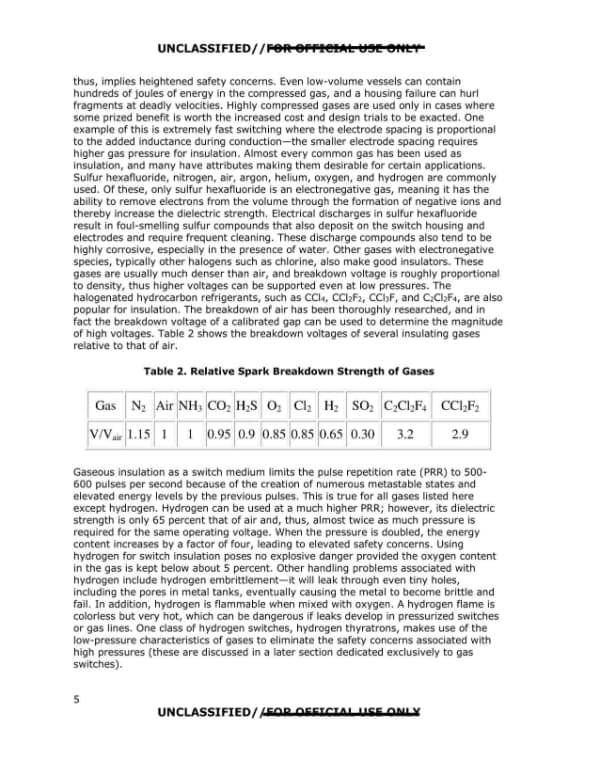
A technical page on gaseous insulation for high-voltage switches, covering properties of sulfur hexafluoride, halogenated gases, and hydrogen, with Table 2 listing relative spark breakdown strengths of several gases. The page is marked UNCLASSIFIED//FOR OFFICIAL USE ONLY and numbered 5.
thus, implies heightened safety concerns. Even low-volume vessels can contain hundreds of joules of energy in the compressed gas, and a housing failure can hurl fragments at deadly velocities. Highly compressed gases are used only in cases where some prized benefit is worth the increased cost and design trials to be exacted. One example of this is extremely fast switching where the electrode spacing is proportional to the added inductance during conduction—the smaller electrode spacing requires higher gas pressure for insulation. Almost every common gas has been used as insulation, and many have attributes making them desirable for certain applications. Sulfur hexafluoride, nitrogen, air, argon, helium, oxygen, and hydrogen are commonly used. Of these, only sulfur hexafluoride is an electronegative gas, meaning it has the ability to remove electrons from the volume through the formation of negative ions and thereby increase the dielectric strength. Electrical discharges in sulfur hexafluoride result in foul-smelling sulfur compounds that also deposit on the switch housing and electrodes and require frequent cleaning. These discharge compounds also tend to be highly corrosive, especially in the presence of water. Other gases with electronegative species, typically other halogens such as chlorine, also make good insulators. These gases are usually much denser than air, and breakdown voltage is roughly proportional to density, thus higher voltages can be supported even at low pressures. The halogenated hydrocarbon refrigerants, such as CCl4, CCl2F2, CCl3F, and C2Cl2F4, are also popular for insulation. The breakdown of air has been thoroughly researched, and in fact the breakdown voltage of a calibrated gap can be used to determine the magnitude of high voltages. Table 2 shows the breakdown voltages of several insulating gases relative to that of air. Table 2. Relative Spark Breakdown Strength of Gases Gas | N2 | Air | NH3 | CO2 | H2S | O2 | Cl2 | H2 | SO2 | C2Cl2F4 | CCl2F2 V/Vair | 1.15 | 1 | 1 | 0.95 | 0.9 | 0.85 | 0.85 | 0.65 | 0.30 | 3.2 | 2.9 Gaseous insulation as a switch medium limits the pulse repetition rate (PRR) to 500-600 pulses per second because of the creation of numerous metastable states and elevated energy levels by the previous pulses. This is true for all gases listed here except hydrogen. Hydrogen can be used at a much higher PRR; however, its dielectric strength is only 65 percent that of air and, thus, almost twice as much pressure is required for the same operating voltage. When the pressure is doubled, the energy content increases by a factor of four, leading to elevated safety concerns. Using hydrogen for switch insulation poses no explosive danger provided the oxygen content in the gas is kept below about 5 percent. Other handling problems associated with hydrogen include hydrogen embrittlement—it will leak through even tiny holes, including the pores in metal tanks, eventually causing the metal to become brittle and fail. In addition, hydrogen is flammable when mixed with oxygen. A hydrogen flame is colorless but very hot, which can be dangerous if leaks develop in pressurized switches or gas lines. One class of hydrogen switches, hydrogen thyratrons, makes use of the low-pressure characteristics of gases to eliminate the safety concerns associated with high pressures (these are discussed in a later section dedicated exclusively to gas switches). UNCLASSIFIED//FOR OFFICIAL USE ONLY 5
Page 14

Page 14 of 37

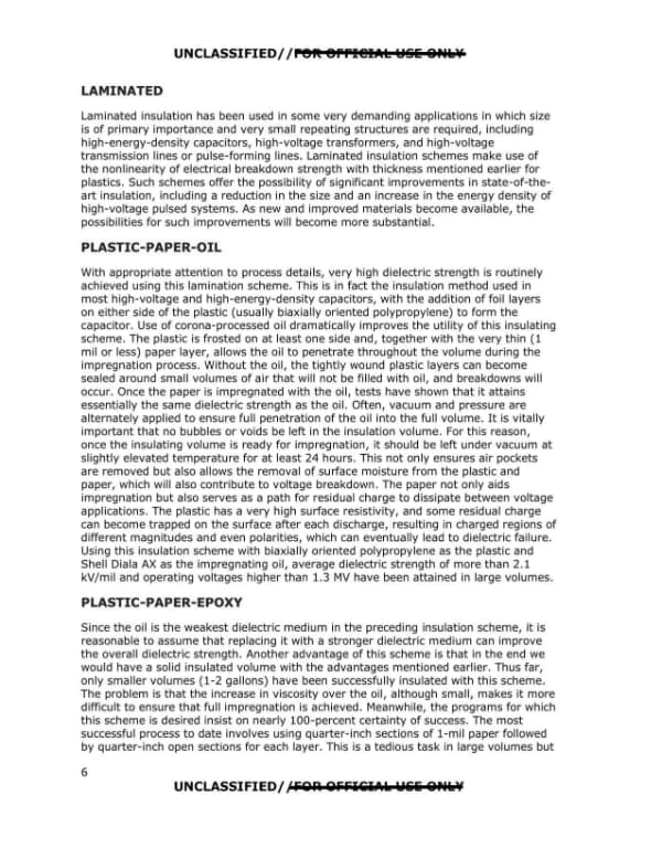
Page 6 of a document on laminated insulation schemes, covering plastic-paper-oil and plastic-paper-epoxy insulation methods and their dielectric strength characteristics. The page is printed with an UNCLASSIFIED//FOR OFFICIAL USE ONLY banner and contains no redactions.
UNCLASSIFIED//FOR OFFICIAL USE ONLY LAMINATED Laminated insulation has been used in some very demanding applications in which size is of primary importance and very small repeating structures are required, including high-energy-density capacitors, high-voltage transformers, and high-voltage transmission lines or pulse-forming lines. Laminated insulation schemes make use of the nonlinearity of electrical breakdown strength with thickness mentioned earlier for plastics. Such schemes offer the possibility of significant improvements in state-of-the-art insulation, including a reduction in the size and an increase in the energy density of high-voltage pulsed systems. As new and improved materials become available, the possibilities for such improvements will become more substantial. PLASTIC-PAPER-OIL With appropriate attention to process details, very high dielectric strength is routinely achieved using this lamination scheme. This is in fact the insulation method used in most high-voltage and high-energy-density capacitors, with the addition of foil layers on either side of the plastic (usually biaxially oriented polypropylene) to form the capacitor. Use of corona-processed oil dramatically improves the utility of this insulating scheme. The plastic is frosted on at least one side and, together with the very thin (1 mil or less) paper layer, allows the oil to penetrate throughout the volume during the impregnation process. Without the oil, the tightly wound plastic layers can become sealed around small volumes of air that will not be filled with oil, and breakdowns will occur. Once the paper is impregnated with the oil, tests have shown that it attains essentially the same dielectric strength as the oil. Often, vacuum and pressure are alternately applied to ensure full penetration of the oil into the full volume. It is vitally important that no bubbles or voids be left in the insulation volume. For this reason, once the insulating volume is ready for impregnation, it should be left under vacuum at slightly elevated temperature for at least 24 hours. This not only ensures air pockets are removed but also allows the removal of surface moisture from the plastic and paper, which will also contribute to voltage breakdown. The paper not only aids impregnation but also serves as a path for residual charge to dissipate between voltage applications. The plastic has a very high surface resistivity, and some residual charge can become trapped on the surface after each discharge, resulting in charged regions of different magnitudes and even polarities, which can eventually lead to dielectric failure. Using this insulation scheme with biaxially oriented polypropylene as the plastic and Shell Diala AX as the impregnating oil, average dielectric strength of more than 2.1 kV/mil and operating voltages higher than 1.3 MV have been attained in large volumes. PLASTIC-PAPER-EPOXY Since the oil is the weakest dielectric medium in the preceding insulation scheme, it is reasonable to assume that replacing it with a stronger dielectric medium can improve the overall dielectric strength. Another advantage of this scheme is that in the end we would have a solid insulated volume with the advantages mentioned earlier. Thus far, only smaller volumes (1-2 gallons) have been successfully insulated with this scheme. The problem is that the increase in viscosity over the oil, although small, makes it more difficult to ensure that full impregnation is achieved. Meanwhile, the programs for which this scheme is desired insist on nearly 100-percent certainty of success. The most successful process to date involves using quarter-inch sections of 1-mil paper followed by quarter-inch open sections for each layer. This is a tedious task in large volumes but 6 UNCLASSIFIED//FOR OFFICIAL USE ONLY
Page 15

Page 15 of 37

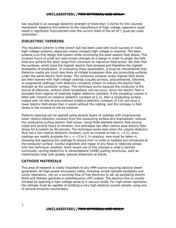
Page 7 of a technical report on pulsed high-power microwave source technology, covering dielectric strength results, the dielectric tapering insulation technique, and the opening of a section on cathode materials. The page contains no redactions.

UNCLASSIFIED//FOR OFFICIAL USE ONLY has resulted in an average dielectric strength of more than 3 kV/mil for the volumes mentioned. Adapting this scheme to the manufacture of high-voltage capacitors could result in significant improvement over the current state of the art of 1 joule per cubic centimeter. DIELECTRIC TAPERING This insulation scheme is little known but has been used with much success in many high-voltage systems, especially where compact high voltage is required. The basic scheme is to first design the system while minimizing the peak electric field stress. This involves hours of small but well-chosen changes to a design in order to shape the field lines and achieve the least range from minimum to maximum field stress. We then find the surfaces, which have the highest electric field stresses and therefore the highest probability of breakdown. In evaluating these parameters, it must be remembered that dielectric media are much less likely to initiate breakdown than are conducting surfaces under the same electric field stress. The conductor surfaces under highest field stress are then layered with high-voltage coatings (usually acrylics, polyurethanes, silicones, or engineered coatings) with dielectric constants chosen to reduce the electric field strength at the conductor surface. This technique works because the conductor is the source of electrons, without which breakdown will not occur. Since the electric field is excluded from regions of relatively higher dielectric constant, if the insulating volume is filled with mineral oil (relative dielectric constant of 2.2), then a conducting surface coated with 10 mils of polyurethane (relative dielectric constant of 3.6) will have a lower electric field stress than it would without the coating, and the increase in field stress in the mineral oil will be minimal. Dialectic tapering can be applied using several layers of coatings with progressively lower relative dielectric constant from the conducting surface and dramatically reduces the conducting surface electric field stress. Using finite element electric field solving codes and several hours of iteration, this technique can often reduce peak electric field stress for a system by 50 percent. The technique works best when the volume dielectric fluid has a low relative dielectric constant, such as mineral oil has (Er =2.2), since coatings are readily available for Er = ~3 to 5. In practice, care must be taken in choosing and applying the coatings to ensure that no voids or bubbles are introduced at the conductor surface. Careful inspection and repair of any flaws is relatively simple with this technique. Another, more recent use of this concept is what is termed continually varying dielectrics in ultrawideband (UWB) guiding structures, such as transmission lines with greatly reduced dispersion at bends. CATHODE MATERIALS This area of research is vitally important to any HPM source requiring electron beam generation. All high-power microwave tubes, including virtual cathode oscillators and cavity resonators, rely on a bunched flow of free electrons to set up oscillating electric fields and thereby generate a radiofrequency (RF) output. The electron flow is usually initiated by applying a high-voltage pulse to a vacuum diode. For high-power operation, the cathode must be capable of emitting a very high electron current density using one of several emission mechanisms. UNCLASSIFIED//FOR OFFICIAL USE ONLY
Page 16

Page 16 of 37

This page is a technical discussion of cathode emission mechanisms and ideal cathode characteristics for high-power microwave (HPM) tubes, marked UNCLASSIFIED//FOR OFFICIAL USE ONLY. It cites J. R. Pierce (1946) for the characteristics of an ideal cathode and lists materials currently under investigation.
These mechanisms include: • Thermionic emission (apply heat – 1,000 °Celsius) • Secondary emission (electron bombardment; > 100 eV) • Field emission (apply a very strong electric field; 107 V/cm) • Explosive emission (form a plasma on the surface; εω= 0) The emission mechanisms of major importance for HPM at present are thermionic emission and explosive electron emission; however, field emission shows some hope with the advancements in nanostructures. Explosive emission, creating a dense plasma at the cathode surface, is of primary importance at this point. A review of pure metals reveals a direct correlation between the work function (εω) and melting temperatures. When cathodes are made from metals with low work functions, there are problems with metal deposition onto other components. Most cathodes of use in HPM tubes depend on a surface flashover at a dielectric-metal interface. The surface flashover generates plasma, typically at tens–of-kilovolts-per-centimeter electric fields. The threshold and nature of the plasma depend greatly on the cathode materials. Therefore, the choice of cathode material is of critical importance in the design and operation of any HPM tube. No discussion of HPM diodes could be complete without mentioning space charge limited current flow. This stems from the fact that at some magnitude of current density, the density of electrons in the anode-cathode gap begins to shield the cathode from further emission owing to their cumulative effect on the electric field at the cathode surface. The current density at which this happens is given by the Child-Langmuir law: Jsc(kA/cm2) = 2.33 x 10⁻⁶ (V(MV)3/2 /d(cm)2) and is dependent on the diode voltage and the anode-cathode spacing. So, if we could have the ideal cathode material, what would its characteristics be? The response has not changed much in more than 60 years, as can be seen in the following extraction from a textbook on the subject. Primary Characteristics of an Ideal Cathode (J. R. Pierce, 1946): • Emits electrons freely, without any form of persuasion such as heating or bombardment (electrons would leak off from it into vacuum as easily as they pass from one metal to another). • Emits copiously, supplying an unlimited current density. • Lasts forever, its electron emission continuing unimpaired as long as it is needed. • Emits electrons uniformly, traveling at practically zero velocity. Efforts are still under way to increase the output power, pulsed emission duration, repetition rate, and emission uniformity by investigating new and existing cathode materials in an effort to draw closer to the ideal cathode. Some of the materials currently being investigated are ceramic cloth and felt, carbon structures including nanotubes and microfibers, and carbon structures coated with cesium iodide. 8
Page 17

Page 17 of 37

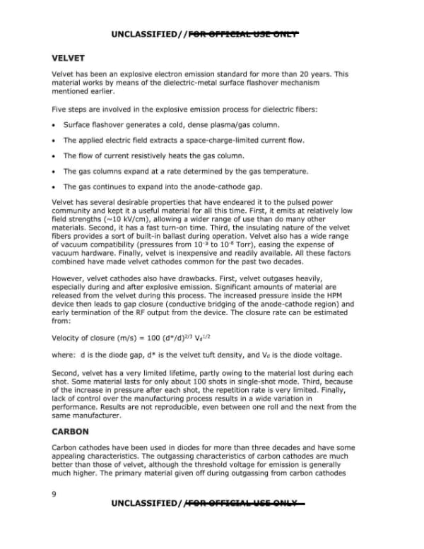
Page 9 of a technical report section comparing explosive electron emission cathode materials, describing the properties and drawbacks of velvet cathodes and beginning a section on carbon cathodes. The page contains no redactions.
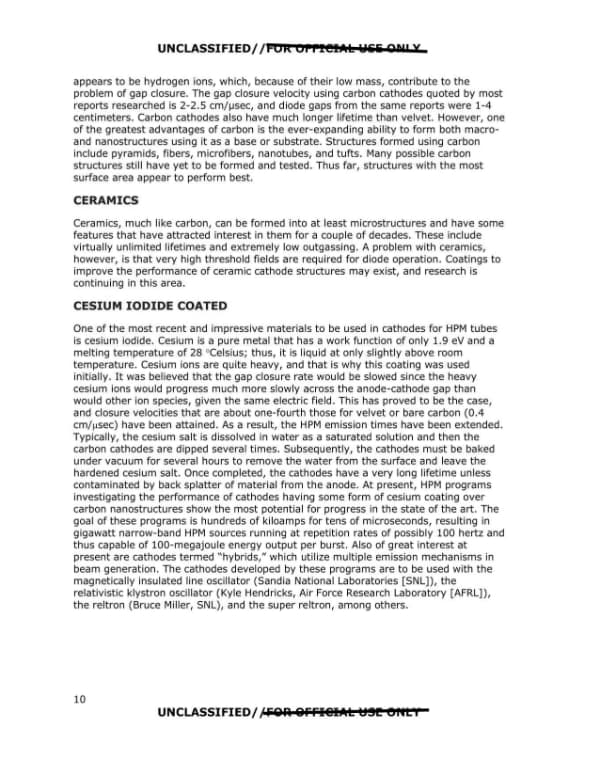
UNCLASSIFIED//FOR OFFICIAL USE ONLY VELVET Velvet has been an explosive electron emission standard for more than 20 years. This material works by means of the dielectric-metal surface flashover mechanism mentioned earlier. Five steps are involved in the explosive emission process for dielectric fibers: • Surface flashover generates a cold, dense plasma/gas column. • The applied electric field extracts a space-charge-limited current flow. • The flow of current resistively heats the gas column. • The gas columns expand at a rate determined by the gas temperature. • The gas continues to expand into the anode-cathode gap. Velvet has several desirable properties that have endeared it to the pulsed power community and kept it a useful material for all this time. First, it emits at relatively low field strengths (~10 kV/cm), allowing a wider range of use than do many other materials. Second, it has a fast turn-on time. Third, the insulating nature of the velvet fibers provides a sort of built-in ballast during operation. Velvet also has a wide range of vacuum compatibility (pressures from 10-3 to 10-8 Torr), easing the expense of vacuum hardware. Finally, velvet is inexpensive and readily available. All these factors combined have made velvet cathodes common for the past two decades. However, velvet cathodes also have drawbacks. First, velvet outgases heavily, especially during and after explosive emission. Significant amounts of material are released from the velvet during this process. The increased pressure inside the HPM device then leads to gap closure (conductive bridging of the anode-cathode region) and early termination of the RF output from the device. The closure rate can be estimated from: Velocity of closure (m/s) = 100 (d*/d)2/3 Vd1/2 where: d is the diode gap, d* is the velvet tuft density, and Vd is the diode voltage. Second, velvet has a very limited lifetime, partly owing to the material lost during each shot. Some material lasts for only about 100 shots in single-shot mode. Third, because of the increase in pressure after each shot, the repetition rate is very limited. Finally, lack of control over the manufacturing process results in a wide variation in performance. Results are not reproducible, even between one roll and the next from the same manufacturer. CARBON Carbon cathodes have been used in diodes for more than three decades and have some appealing characteristics. The outgassing characteristics of carbon cathodes are much better than those of velvet, although the threshold voltage for emission is generally much higher. The primary material given off during outgassing from carbon cathodes 9 UNCLASSIFIED//FOR OFFICIAL USE ONLY
Page 18

Page 18 of 37

This is a page of a technical report on cathode materials for pulsed high-power microwave tubes, covering carbon, ceramic and cesium iodide coated cathodes. It describes gap closure velocities, cathode lifetimes and the programs and laboratories using these cathodes.
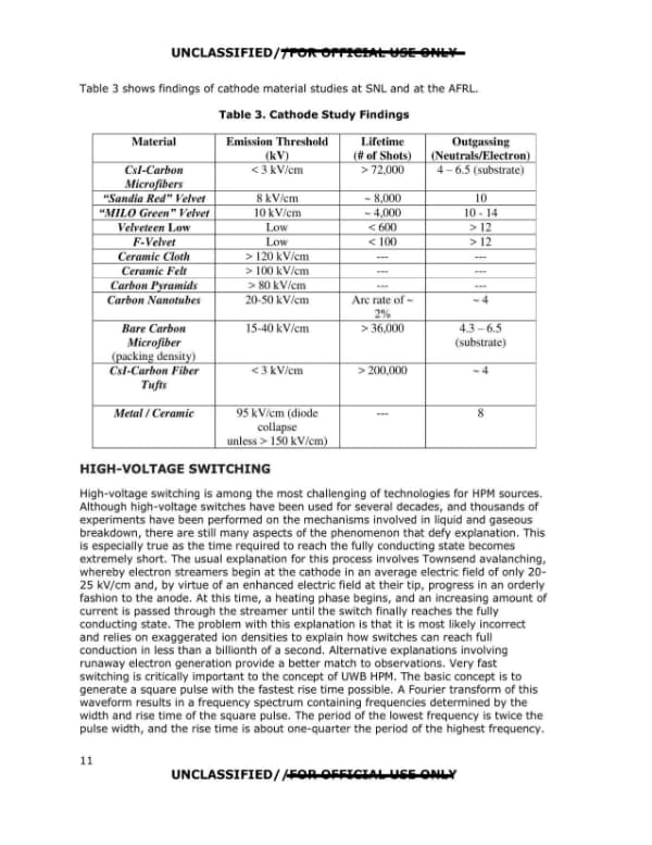
appears to be hydrogen ions, which, because of their low mass, contribute to the problem of gap closure. The gap closure velocity using carbon cathodes quoted by most reports researched is 2-2.5 cm/µsec, and diode gaps from the same reports were 1-4 centimeters. Carbon cathodes also have much longer lifetime than velvet. However, one of the greatest advantages of carbon is the ever-expanding ability to form both macro- and nanostructures using it as a base or substrate. Structures formed using carbon include pyramids, fibers, microfibers, nanotubes, and tufts. Many possible carbon structures still have yet to be formed and tested. Thus far, structures with the most surface area appear to perform best. CERAMICS Ceramics, much like carbon, can be formed into at least microstructures and have some features that have attracted interest in them for a couple of decades. These include virtually unlimited lifetimes and extremely low outgassing. A problem with ceramics, however, is that very high threshold fields are required for diode operation. Coatings to improve the performance of ceramic cathode structures may exist, and research is continuing in this area. CESIUM IODIDE COATED One of the most recent and impressive materials to be used in cathodes for HPM tubes is cesium iodide. Cesium is a pure metal that has a work function of only 1.9 ev and a melting temperature of 28 °Celsius; thus, it is liquid at only slightly above room temperature. Cesium ions are quite heavy, and that is why this coating was used initially. It was believed that the gap closure rate would be slowed since the heavy cesium ions would progress much more slowly across the anode-cathode gap than would other ion species, given the same electric field. This has proved to be the case, and closure velocities that are about one-fourth those for velvet or bare carbon (0.4 cmh1sec) have been attained. As a result, the HPM emission times have been extended. Typically, the cesium salt is dissolved in water as a saturated solution and then the carbon cathodes are dipped several times. Subsequently, the cathodes must be baked under vacuum for several hours to remove the water from the surface and leave the hardened cesium salt. Once completed, the cathodes have a very long lifetime unless contaminated by back splatter of material from the anode. At present, HPM programs investigating the performance of cathodes having some form of cesium coating over carbon nanostructures show the most potential for progress in the state of the art. The goal of these programs is hundreds of kiloamps for tens of microseconds, resulting in gigawatt narrow-band HPM sources running at repetition rates of possibly 100 hertz and thus capable of 100-megajoule energy output per burst. Also of great interest at present are cathodes termed "hybrids," which utilize multiple emission mechanisms in beam generation. The cathodes developed by these programs are to be used with the magnetically insulated line oscillator (Sandia National Laboratories [SNL]), the relativistic klystron oscillator (Kyle Hendricks, Air Force Research Laboratory [AFRL]), the reltron (Bruce Miller, SNL), and t he super reltron, among others. UNCLASSIFIED//FOR OFFICIAL USE ONLY 10 UNCLASSIFIED//FOR OFFICIAL USE ONLY
Page 19

Page 19 of 37

A page from a technical report presenting Table 3, cathode material study findings from SNL and AFRL, followed by a section on high-voltage switching for HPM sources. The page carries the report's UNCLASSIFIED/FOR OFFICIAL USE ONLY markings and page number 11.
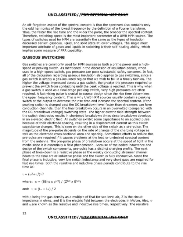
UNCLASSIFIED/ /FOR OFFICIAL USE ONLY Table 3 shows findings of cathode material studies at SNL and at the AFRL. Table 3. Cathode Study Findings Material | Emission Threshold (kV) | Lifetime (# of Shots) | Outgassing (Neutrals/Electron) CsI-Carbon Microfibers | < 3 kV/cm | > 72,000 | 4 - 6.5 (substrate) "Sandia Red" Velvet | 8 kV/cm | ~ 8,000 | 10 "MILO Green" Velvet | 10 kV/cm | ~ 4,000 | 10 - 14 Velveteen Low | Low | < 600 | > 12 F-Velvet | Low | < 100 | > 12 Ceramic Cloth | > 120 kV/cm | --- | --- Ceramic Felt | > 100 kV/cm | --- | --- Carbon Pyramids | > 80 kV/cm | --- | --- Carbon Nanotubes | 20-50 kV/cm | Arc rate of ~ 2% | ~ 4 Bare Carbon Microfiber (packing density) | 15-40 kV/cm | > 36,000 | 4.3 - 6.5 (substrate) CsI-Carbon Fiber Tufts | < 3 kV/cm | > 200,000 | ~ 4 Metal / Ceramic | 95 kV/cm (diode collapse unless > 150 kV/cm) | --- | 8 HIGH-VOLTAGE SWITCHING High-voltage switching is among the most challenging of technologies for HPM sources. Although high-voltage switches have been used for several decades, and thousands of experiments have been performed on the mechanisms involved in liquid and gaseous breakdown, there are still many aspects of the phenomenon that defy explanation. This is especially true as the time required to reach the fully conducting state becomes extremely short. The usual explanation for this process involves Townsend avalanching, whereby electron streamers begin at the cathode in an average electric field of only 20-25 kV/cm and, by virtue of an enhanced electric field at their tip, progress in an orderly fashion to the anode. At this time, a heating phase begins, and an increasing amount of current is passed through the streamer until the switch finally reaches the fully conducting state. The problem with this explanation is that it is most likely incorrect and relies on exaggerated ion densities to explain how switches can reach full conduction in less than a billionth of a second. Alternative explanations involving runaway electron generation provide a better match to observations. Very fast switching is critically important to the concept of UWB HPM. The basic concept is to generate a square pulse with the fastest rise time possible. A Fourier transform of this waveform results in a frequency spectrum containing frequencies determined by the width and rise time of the square pulse. The period of the lowest frequency is twice the pulse width, and the rise time is about one-quarter the period of the highest frequency. 11 UNCLASSIFIED/ /FOR OFFICIAL USE ONLY
Page 20

Page 20 of 37

Page 12 of a technical discussion of pulsed high-power microwave source switching, covering gaseous switch behavior, peaking switches, pre-pulse, and rise-time equations. The page ends mid-sentence describing the resistive rise time.
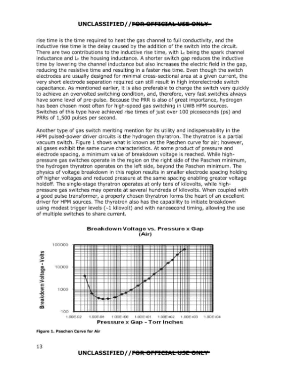
UNCLASSIFIED//FOR OFFICIAL USE ONLY An oft-forgotten aspect of the spectral content is that the spectrum also contains only the odd harmonics of the lowest frequency by the definition of a Fourier transform. Thus, the faster the rise time and the wider the pulse, the broader the spectral content. Therefore, switching speed is the most important parameter of a UWB HPM source. The types of switches used for HPM are essentially the same as the types of insulation discussed earlier: gaseous, liquid, and solid state at lower voltages. The single most important attribute of gases and liquids in switching is their self-healing ability, which implies some measure of PRR capability. GASEOUS SWITCHING Gas switches are commonly used for HPM sources as both a prime power and a high-speed or peaking switch. As mentioned in the discussion of insulation earlier, when used in a high-speed switch, gas pressure can pose substantial safety concerns. In fact, all of the discussion regarding gaseous insulation also applies to gas switching, since a gas switch is simply a gas-insulated region that we wish to fail in a timely fashion. The higher the voltage impressed across a gas switch, the greater the pressure required to prevent the switch from conducting until the peak voltage is reached. This is why when a gas switch is used as a final-stage peaking switch, very high pressures are often required. A fast-rising pulse is crucial to source design since the rise time determines the upper frequency content. This is why UWB HPM sources usually contain a peaking switch at the output to decrease the rise time and increase the spectral content. If the peaking switch is charged past the DC breakdown level faster than streamers can form conduction channels, then the final breakdown occurs in an overvolted (compared with the DC breakdown voltage) switching state. The higher electric field strength between the switch electrodes results in shortened breakdown times since breakdown develops in an elevated electric field. All switches exhibit some capacitance to an applied pulse because of their electrode spacing, resulting in a displacement current as this switch capacitance charges. This is seen on the other side of the switch as a pre-pulse. The magnitude of the pre-pulse depends on the rate of change of the charging voltage as well as the electrode cross-sectional area and spacing. Sometimes efforts to reduce this pre-pulse are required if it causes problems at the load or undesired spectral content from the antenna. The pre-pulse phase of breakdown occurs at the speed of light in the media since it is essentially a field phenomenon. Because of the added inductance and design of the switch components, pre-pulse has a distinct charging profile. The next phase of breakdown is a resistive phase as the weakly conducting streamer channel heats to the final arc or inductive phase and the switch is fully conductive. Since the final phase is inductive, very low switch inductance and very short gaps are required for fast rise times. Both the resistive and inductive phase periods contribute to the rise time as: τ = (τr² + τL²)^1/2 where: τr = (88ns x ρ^1/2) / (Z^1/3 x E^4/3) and: τL = (Lc + Lh) / Z with ρ being the gas density as a multiple of that for sea level air, Z is the circuit impedance in ohms, and E is the electric field between the electrodes in kV/cm. Also, τr and τL are known as the resistive and inductive rise times, respectively. The resistive 12 UNCLASSIFIED//FOR OFFICIAL USE ONLY
Page 21

Page 21 of 37

Not read yet.

Page 22

Page 22 of 37

Not read yet.

Page 23

Page 23 of 37

Not read yet.

Page 24

Page 24 of 37

Not read yet.