$DECLASSwnMfUvY5KfUN2LbKgyHXwmh39mGpJd7bjJw5A71pumpBuy
Declassified
Releases / Release 06 / DOW-UAP-D120
Department of War

AAWSAP DIRD, Materials for Advanced Aerospace Platforms, January 2010

This document is a Defense Intelligence Reference Document (DIRD), a technical reference format used by the Defense Intelligence Agency (DIA) to capture baseline knowledge on a specific topic for later analytic use. DIRDs are best understood as reference and synthesis products rather than as original research. It is one of 38 DIRDs produced under the Advanced Aerospace Weapon System Applications Program (AAWSAP) between 2009 and 2011. Because AAWSAP’s scope permitted a broad range of supporting topics, not every DIRD in the series directly concerns aerospace systems or future threat assessment. The following summary reflects the DIRD’s scope and framing at the time of writing and should…

Catalogue description by the publishing agency.

Record
DOW-UAP-D120
Release
Release 06 · Sep 18, 2026
Incident
2010-01-12 · Las Vegas, Nevada
Pages
27
Verdict
not judged yet
Source
war.gov ↗
Page by page

The pages and what the AI read on them

The transcription is the page reader's: black bars mark what the government redacted; hatched tags mark personal data we removed.

Page 1

Page 1 of 27

This is the cover page of a Defense Intelligence Reference Document titled "Materials for Advanced Aerospace Platforms," dated 12 January 2010, with ICOD 1 December 2009 and document number DIA-08-0912-008. The page is marked UNCLASSIFIED//FOR OFFICIAL USE ONLY and bears the Defense Intelligence Agency seal.

UNCLASSIFIED//FOR OFFICIAL USE ONLY Defense Intelligence Reference Document Acquisition Threat Support 12 January 2010 ICOD: 1 December 2009 DIA-08-0912-008 Materials for Advanced Aerospace Platforms UNCLASSIFIED//FOR OFFICIAL USE ONLY
Page 2

Page 2 of 27 · 1 redaction

This is the title and administrative note page of a Defense Intelligence Agency report titled Materials for Advanced Aerospace Platforms, prepared under the AAWSA Program in FY 2009. It contains a copyright warning and directs questions to the AAWSA Program Manager.
UNCLASSIFIED//FOR OFFICIAL USE ONLY Materials for Advanced Aerospace Platforms Prepared by: Acquisition Support Division (DWO-3) Defense Warning Office Directorate for Analysis Defense Intelligence Agency Author: AAP Person 66 Administrative Note COPYRIGHT WARNING: Further dissemination of the photographs in this publication is not authorized. This product is one in a series of advanced technology reports produced in FY 2009 under the Defense Intelligence Agency, Defense Warning Office's Advanced Aerospace Weapon System Applications (AAWSA) Program. Comments or questions pertaining to this document should be addressed to [REDACTED] AAWSA Program Manager, Defense Intelligence Agency, ATTN: CLAR/DWO-3, Bldg 6000, Washington, DC 20340-5100. ii UNCLASSIFIED//FOR OFFICIAL USE ONLY
Page 3

Page 3 of 27

This is the table of contents page of a report on materials for advanced aerospace platforms, listing sections, figures and tables with page numbers. The page is marked UNCLASSIFIED//FOR OFFICIAL USE ONLY and is numbered iii.
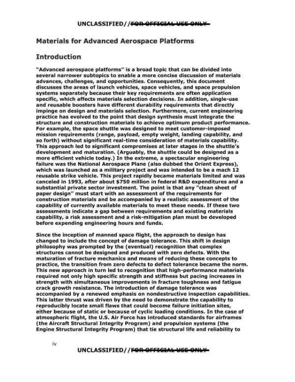
UNCLASSIFIED//FOR OFFICIAL USE ONLY Contents Introduction ...........................................................................................................iv Launch Vehicles ................................................................................................. 1 Reusable Crew Modules...................................................................................... 9 Reusable Single-Stage-to-Orbit Vehicles ...................................................... 10 Advanced Al Alloys ....................................................................................... 11 Polymer Matrix Composites .......................................................................... 11 Al Matrix Composites.................................................................................... 12 Ti Alloys ....................................................................................................... 12 Ti Matrix Composites .................................................................................... 14 Ni-base Alloys .............................................................................................. 16 Refractory Metal Alloys ................................................................................ 18 Ceramic Matrix Composites .......................................................................... 18 Carbon-Carbon Composites .......................................................................... 19 Titanium Aluminides .................................................................................... 20 Propulsion Systems.......................................................................................... 21 Summary and Recommendations ..................................................................... 22 Figures 1. Schematic Diagram of Friction Stir Welding ....................................................... 2 2. Specially Modified 747 Transporter Unloading a Boeing 787 Composite Fuselage Barrel Section ..................................................................................... 4 3. Micrograph Showing Phase Formation at the Surface of a Ti Alloy That has Been Exposed to Air at Elevated Temperature ................................................. 13 4. Cross-Section Micrograph of a Ti Matrix Composite .......................................... 15 Tables 1. Potential Materials by Use Temperature Regime and Property ......................... 10 2. Example of Properties of Ti Matrix Composites ................................................ 14 iii UNCLASSIFIED//FOR OFFICIAL USE ONLY
Page 4

Page 4 of 27

This is page iv of a DIRD report titled "Materials for Advanced Aerospace Platforms" (January 2010), containing the Introduction discussing materials requirements, the National Aerospace Plane cancellation, and damage tolerance in aerospace design. The page is marked UNCLASSIFIED//FOR OFFICIAL USE ONLY and has no redactions.
UNCLASSIFIED//FOR OFFICIAL USE ONLY Materials for Advanced Aerospace Platforms Introduction "Advanced aerospace platforms" is a broad topic that can be divided into several narrower subtopics to enable a more concise discussion of materials advances, challenges, and opportunities. Consequently, this document discusses the areas of launch vehicles, space vehicles, and space propulsion systems separately because their key requirements are often application specific, which affects materials selection decisions. In addition, single-use and reusable boosters have different durability requirements that directly impinge on design and materials selection. Furthermore, current engineering practice has evolved to the point that design synthesis must integrate the structure and construction materials to achieve optimum product performance. For example, the space shuttle was designed to meet customer-imposed mission requirements (range, payload, empty weight, landing capability, and so forth) without significant real-time consideration of materials capability. This approach led to significant compromises at later stages in the shuttle's development and maturation. (Arguably, the shuttle could be designed as a more efficient vehicle today.) In the extreme, a spectacular engineering failure was the National Aerospace Plane (also dubbed the Orient Express), which was launched as a military project and was intended to be a mach 12 reusable strike vehicle. This project rapidly became materials limited and was canceled in 1993, after about $750 million in federal R&D expenditures and a substantial private sector investment. The point is that any "clean sheet of paper design" must start with an assessment of the requirements for construction materials and be accompanied by a realistic assessment of the capability of currently available materials to meet these needs. If these two assessments indicate a gap between requirements and existing materials capability, a risk assessment and a risk-mitigation plan must be developed before expending engineering hours and funds. Since the inception of manned space flight, the approach to design has changed to include the concept of damage tolerance. This shift in design philosophy was prompted by the (eventual) recognition that complex structures cannot be designed and produced with zero defects. With the maturation of fracture mechanics and means of reducing these concepts to practice, the transition from zero defects to defect tolerance became the norm. This new approach in turn led to recognition that high-performance materials required not only high specific strength and stiffness but pacing increases in strength with simultaneous improvements in fracture toughness and fatigue crack growth resistance. The introduction of damage tolerance was accompanied by a renewed emphasis on nondestructive inspection capabilities. This latter thrust was driven by the need to demonstrate the capability to reproducibly locate small flaws that could become failure initiation sites, either because of static or because of cyclic loading conditions. In the case of atmospheric flight, the U.S. Air Force has introduced standards for airframes (the Aircraft Structural Integrity Program) and propulsion systems (the Engine Structural Integrity Program) that tie structural life and reliability to iv UNCLASSIFIED//FOR OFFICIAL USE ONLY
Page 5

Page 5 of 27

This is a page of a report on materials for advanced aerospace platforms, consisting of two paragraphs describing the effect of inspection standards on catastrophic component failures and outlining the scope of the document. The page is marked UNCLASSIFIED//FOR OFFICIAL USE ONLY and bears the page number V.

UNCLASSIFIED//FOR OFFICIAL USE ONLY this demonstrated inspections capability. Implementation of these standards, starting with the B-1 bomber and the F-100 and F-110 engines, has dramatically reduced (but not eliminated) the incidence of catastrophic failures of critical components that endanger crews, vehicles, or both. Taking these changes into account, this document outlines the current situation regarding the design and production of high-performance structures for aerospace platforms, including launch vehicles, space vehicles, and propulsion systems for transporting space vehicles (and payloads) into orbit. V UNCLASSIFIED//FOR OFFICIAL USE ONLY
Page 6

Page 6 of 27

Page 1 of a document titled 'Materials for Advanced Aerospace Platforms', section 'Launch Vehicles', discussing the use of advanced aluminum alloys and carbon fiber composites in launch vehicle structures and the fracture toughness benefits of improved Al alloys.

UNCLASSIFIED/ /FOR OFFICIAL USE ONLY Materials for Advanced Aerospace Platforms LAUNCH VEHICLES For the purposes of this document, launch vehicles are defined as the structure that supports and/or encloses the propulsion system, the fuel supply, and the crew or payload module. Launch vehicles today are either single use or multiple use after recovery and extensive refurbishment. This approach adds considerably to the cost of transporting a pound of payload into earth orbit, regardless of whether an unmanned satellite or a manned orbiting crew module that must withstand the temperatures and loads associated with safe reentry to earth. Furthermore, the larger the payloads are, the greater are the reaction forces the launch vehicle must withstand during launch. With the total weight of the payload, the empty weight of the launch vehicle, and fuel all needing to be lifted initially, fuel-efficient propulsion and lightweight launch vehicles are essential to maximizing the payload. Except in the area around the propulsion system exhaust, the temperatures experienced by launch vehicles during launch are not demanding. Therefore, advanced, high-strength aluminum (Al) alloys and polymer matrix carbon fiber composites (PMCs) are prime candidates for the parts of the structure that experience aerodynamic loads and where aerodynamic heating does not exceed about 125 °Celsius. One class of advanced Al alloys is the lithium (Li)-bearing alloys, such as Al alloy 2090. This alloy contains enough Li to reduce its density by 8 percent while increasing the elastic modulus (E) by 10 percent. Other, newer advanced Al alloys, such as 7050 and 2050, have been developed to have improved damage tolerance. These alloys have excellent specific strength at or near room temperature and experience no major loss of ductility at cryogenic temperatures. The newer variants of the 2000 and 7000 Al alloys also have substantially improved resistance to most types of corrosion, including exfoliation and stress corrosion cracking. This can be important in a reusable vehicle. Perhaps the most important aspect of the improved Al alloys is their higher fracture toughness, accomplished through a combination of alloy composition control and improved processing. In alloy composition control, the concentrations of the residual elements iron (Fe), chromium (Cr), manganese (Mn), and silicon (Si) are reduced at the ingot stage. These elements combine with Al to form hard, brittle intermetallic compounds known as constituent phases. The advanced alloys contain fewer, smaller constituent phases, leading to improved fracture resistance and higher fracture toughness values. In applications such as body skins for commercial aircraft, this improved toughness has enabled an increase in the spacing of the circumferential fuselage frames, or "hat sections," that serve both as stiffeners and as crack stoppers to prevent a catastrophic failure during pressurization. For any given operating stress-in this case the pressurization stress-the spacing of the frames is directly related to the critical crack size of the body skin. Higher toughness alloys have larger critical crack sizes, and the frames can be spaced further apart without increasing the risk of catastrophic failure. The increased spacing ultimately allows a fuselage design that requires fewer frames. Consequently, the airplane benefits from a commensurate reduction both in weight and in manufacturing cost. Similar possibilities exist for the design of a fail-safe launch vehicle that has a lower empty weight. Clearly, the advanced Al alloys offer intrinsic improvements over the alloys used in the Saturn launch vehicle and introduce the prospect of new, more efficient launch vehicle designs. 1 UNCLASSIFIED/ /FOR OFFICIAL USE ONLY
Page 7

Page 7 of 27

Not read yet.

Page 8

Page 8 of 27

This page is a numbered page 3 of a technical report discussing advanced aluminum alloys, friction stir welding, and polymer matrix composites (PMCs) for launch vehicles and aircraft, and describing hand layup of pre-preg composite manufacturing. The page contains no redactions.
construction to be considered too risky. Today, the combination of higher toughness alloys and FSW opens up the possibility of greater design flexibility resulting in lighter large structures with equal or greater reliability than earlier ones. In sum, metallic, nonreusable (at least nominally so) launch vehicles made from advanced Al alloys and fabricated through FSW constitute an incremental but significant improvement over earlier versions. In recent years, PMCs have matured significantly. For many components that are not exposed to elevated temperatures, PMCs provide a degree of design flexibility not readily available in metals. Consequently, PMC materials have begun to supplant Al alloys in the construction of commercial subsonic aircraft. The use of PMCs in the empennage of the Boeing 777 was one of the first examples of Al alloys being displaced. Subsequently, the new Boeing 787 has more structure made from composites than from metallic materials. Once PMCs are introduced into a structure in significant quantities, a constraint related to galvanic incompatibility between the PMC structure and any adjoining Al alloys also is introduced. When a PMC structure is in direct contact with an Al alloy structure, catastrophic corrosion of the Al alloy components can occur. In the Boeing 787, the remedy for this concern is the use of titanium (Ti) alloys in areas where there is direct contact between the metallic and the PMC structures. This is directly analogous to the plastic bushing a plumber puts in the joint between copper and iron piping. Notwithstanding this constraint, the specific strength and stiffness of PMC structures make a compelling argument for their application in high-performance structures, such as launch vehicles. Composite structures can be manufactured using one of three methods: hand layup of pre-preg, automated tow placement, and resin transfer molding. The most rudimentary of these, but also the most flexible, is hand layup of pre-preg. This method uses sheets of material that contain both the fiber and the polymeric matrix (called pre-preg). The polymeric matrix can be either a thermoset (for example, epoxy) or a thermoplastic. Individual plies are cut from the pre-preg typically using a numerically controlled laser or mechanical cutting device and are laid up to form the desired shape. Areas that have heavier loads contain more plies locally, and the plies are cut in an orientation with respect to the fiber direction in the pre-preg to achieve the desired strength relative to the principal load path. These plies are carefully placed according to a drawing (blueprint), making hand layup a labor-intensive process and, therefore, making parts made using this method expensive. During ply placement, it is critical that no ply wrinkles are introduced, as these create severe reductions in the local load-bearing capability of the final component. Once all the plies are in their proper places, the article is placed in a vacuum-tight bag that is evacuated and placed in an autoclave for curing of the epoxy matrix or fusing of the thermoplastic. A disadvantage of a pre-preg whose matrix is a thermoset is limited shelf life. In practice, this is managed to a degree by storing the pre-preg in a freezer to slow the rate of chemical reaction that sets the epoxy. However, this does not completely halt the reaction, causing these materials to have a shelf life beyond which they are not easily manipulated during layup and do not develop full strength after curing in the autoclave. An additional issue is out time\u2014the time the pre-preg can be out of the freezer during layup before the reaction proceeds at an accelerated rate and reaches a point at which the 3
Page 9

Page 9 of 27

A technical page on composite fabrication methods (automated tow placement, compression, and resin transfer molding) with a photo of a 747 Dreamlifter unloading a Boeing 787 fuselage barrel section. The text states that automated tow placement suits axisymmetric shapes and that complex shapes are still mostly hand layup.
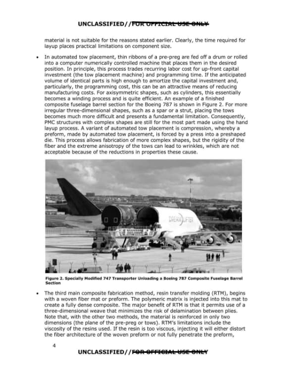
material is not suitable for the reasons stated earlier. Clearly, the time required for layup places practical limitations on component size. • In automated tow placement, thin ribbons of a pre-preg are fed off a drum or rolled into a computer numerically controlled machine that places them in the desired position. In principle, this process trades recurring labor cost for up-front capital investment (the tow placement machine) and programming time. If the anticipated volume of identical parts is high enough to amortize the capital investment and, particularly, the programming cost, this can be an attractive means of reducing manufacturing costs. For axisymmetric shapes, such as cylinders, this essentially becomes a winding process and is quite efficient. An example of a finished composite fuselage barrel section for the Boeing 787 is shown in Figure 2. For more irregular three-dimensional shapes, such as a spar or a strut, placing the tows becomes much more difficult and presents a fundamental limitation. Consequently, PMC structures with complex shapes are still for the most part made using the hand layup process. A variant of automated tow placement is compression, whereby a preform, made by automated tow placement, is forced by a press into a preshaped die. This process allows fabrication of more complex shapes, but the rigidity of the fiber and the extreme anisotropy of the tows can lead to wrinkles, which are not acceptable because of the reductions in properties these cause. Figure 2. Specially Modified 747 Transporter Unloading a Boeing 787 Composite Fuselage Barrel Section • The third main composite fabrication method, resin transfer molding (RTM), begins with a woven fiber mat or preform. The polymeric matrix is injected into this mat to create a fully dense composite. The major benefit of RTM is that it permits use of a three-dimensional weave that minimizes the risk of delamination between plies. Note that, with the other two methods, the material is reinforced in only two dimensions (the plane of the pre-preg or tows). RTM's limitations include the viscosity of the resins used. If the resin is too viscous, injecting it will either distort the fiber architecture of the woven preform or not fully penetrate the preform, 4 UNCLASSIFIED//FOR OFFICIAL USE ONLY
Page 10

Page 10 of 27

A page of a 2010 technical report discussing limitations of resin transfer molding and manufacturing challenges for large polymer matrix composite (PMC) structures, with examples from the Boeing 787 fuselage and GE90 fan blades. The page has no redactions and is numbered 5.
leaving voids. This limitation makes it difficult to use many thermoplastic resins that are otherwise attractive because they are recyclable and have much longer shelf lives than thermosets (epoxies). Another, more obvious limitation of RTM is component size. This is in part because weaving of very large fiber preforms is challenging and requires a very large weaving machine. It also requires a large injection machine capable of multiple injection sites to ensure the complete infiltration necessary to avoid formation of voids. In practice, there are several significant challenges associated with manufacturing large PMC structures today. Among these, perhaps the most significant are manufacturing cost and the difficulty associated with making large, nonaxisymmetric components. Large axisymmetric components that can be produced by winding tows of pre-preg are clearly possible today, as demonstrated by the Boeing 787 fuselage whose section is shown in Figure 2. For other shapes, because the load-bearing capability of PMCs depends on the transfer of externally imposed loads to the strong, stiff fibers, joints that intersect the principal load path become problematic. This is because the fibers and, as a direct consequence, the load path are discontinuous, requiring local section size adjustments to offset this local structural inefficiency. Thus, achieving the most structurally efficient use of PMCs requires monolithic structures with continuous fibers. In large structures, this is at best a challenge. Even in the Boeing 787's PMC fuselage, mechanically fastened joints are used to connect adjacent barrel sections. In the fuselage, as in any cylindrical pressure vessel, the principal stresses are hoop stresses stemming from pressurization during flight. However, the compromise in structural efficiency is minimized by the circumferential orientation of the joints. Although these bolted joints add weight, the overall structural efficiency of the PMC structure is still better, albeit considerably more expensive, than a longitudinally and circumferentially stiffened Al structure. The circumferential joints also create discontinuous longitudinal crack paths that improve the structure's damage tolerance. Some of the added expense of the PMC fuselage stems from the use of Ti alloy fasteners because of the galvanic coupling issues that would accompany Al or steel fasteners. For other applications, which are limited by different material properties, the PMC system can be tailored to optimize structural performance. This is possible because both the matrix and the fiber can be independently selected. Moreover, the fiber "architecture" (fiber orientation, weave geometry, and fiber volume fraction) can be varied spatially to optimize load-bearing capability under complex stress states. For example, again drawing on recent applications in commercial aircraft, the fan blades of the large, high-bypass-ratio turbofan engine (GE90) produced by General Electric for the Boeing 777 are made from PMCs. The limiting design consideration for these fan blades is resistance to bird strikes. To optimize the PMCs' impact resistance, a medium-modulus, high-tensile-strength carbon fiber was selected in combination with a thermoplastic toughened epoxy matrix. Furthermore, the fiber architecture was set to optimize the bending strength under the impact of a bird. The GE90 fan blades are produced by hand layup and are quite costly to produce. In the 10-plus years that these fan blades have been in service, not a single unscheduled engine removal related to the PMC fan blades has occurred. The competitive fan blade technology for B-777-class engines is hollow Ti, which is used by both Pratt & Whitney and Rolls Royce. By all informal accounts, these blades are cost intensive. This example supports the unwritten rule that the pathways leading to high-performance, high-value structures typically are 5
Page 11

Page 11 of 27 · 1 redaction

A technical page from a materials report discussing compression-after-impact delamination in polymer matrix composites, thermal oxidative stability limits of resin classes, and the difficulties small companies face in scaling new resins. The page header and footer are marked UNCLASSIFIED with a struck-through FOR OFFICIAL USE ONLY legend.
not technology dependent but are cost intensive, no matter what technology is employed to meet the requirements. An additional characteristic of PMC structures-one related to the laminated construction of components made by hand layup or automated tow placement methods-is their susceptibility to formation of delaminations when impacted perpendicular to the plane of the plies. This is due to the mismatch in bending stiffness between adjacent plies that have different unidirectional fiber orientations. This mismatch causes shear stresses to develop that can exceed the shear strength of the interlaminate bonds, causing small, embedded cracks to form. Under subsequent inplane compression loading, the laminates bow because of the Poisson stresses and separate because of the lack of an interlaminar bond to hold them together. In significant compression loads, the laminates buckle, and this leads to structural failure. This phenomenon, called compression after impact, is an insidious failure mode because the delaminations are not externally detectable unless ultrasonic inspection methods are used. Sources of such an impact include dropped tools, foreign objects (for example, meteorites), and, perhaps most commonly, hail storms. Ultrasonic inspection, if required, is expensive and time consuming. The latter concern in turn affects vehicle availability and turnaround time. PMC parts made using RTM typically have reinforcing fibers in the through-thickness direction, so concerns about compression after impact are minimal. The maximum temperature at which PMCs can be used is limited by PMCs' susceptibility to oxygen degradation of the polymeric matrix. The maximum-use temperature for prolonged exposure is determined by the thermal oxidative stability (TOS) of a particular resin. The TOS, like any chemical reaction, is determined by both time and temperature. The glass transition temperature (Tg) of the polymeric matrix also imposes strength and dimensional stability limitations independent of the TOS limits. This is particularly true for thermoplastics. However, the TOS limits usually impose lower temperature limits than Tg if prolonged thermal exposure is contemplated. Three distinct classes or groups of resins exist, each with a successively higher temperature capability. These are conventional epoxies and most thermal plastics, bismaleimides (BMIs), and linear polyimides. The first class is limited by TOS to about 125° Celsius. BMIs can be used to about 175° Celsius. Linear polyimides, such as the in situ polymerization of monomer reactants (PMR) group of thermosetting formulations, can be used to about 300° Celsius. Many of the PMR resins contain the hazardous compound methylenedianiline, which requires special care during use, including protective clothing to limit personnel exposure (for example, during ply cutting and hand layup). This requirement reduces productivity, adds cost, and creates a degree of liability concern for the manufacturer of the PMC components. For RTM, the BMIs and PMR resins typically have higher viscosity and require commensurately higher injection temperatures to reduce the viscosity to manageable levels for reasons discussed earlier. New resins are constantly being developed, including some with attractive properties. However, many of the sources of these resins are startup companies that exist on R&D funding, often in the form of U.S. government SBIR (Small Business Innovative Research) projects. Such companies are good at innovation but often have limited experience transitioning new products from the laboratory to large-scale production. Furthermore, in the current economic climate, access to sufficient capital to set up production-scale capacity can be a formidable problem for a small company. Larger companies (for example, BASF, DuPont, GE Plastics) typically are not interested 6 UNCLASSIFIED//[REDACTED]
Page 12

Page 12 of 27

A page from a materials assessment discussing the commercial feasibility of new materials and the use of titanium alloys in structural applications such as bomber wing boxes, landing gear, and launch vehicles. It is marked UNCLASSIFIED with a struck-through 'FOR OFFICIAL USE ONLY' legend and carries page number 7.

UNCLASSIFIED// POI\ OPPICl"L U.!I! Oflt I in materials with small annual sales volume, so even licensing the new material to one of these companies may not be commercially feasible . This foregoing discussion highlights a commonly encountered inconsistency between technical innovation and commercial progress. Until a production-scale source exists, pricing of new materials is at best highly uncertain and potentially unstable over time. This is in part due to the uncertainty surrounding demand and the associated volume of material that will be required. Taken together, these factors act as a clear deterrent to the adoption of new materials of literally all classes (polymers, metals, and ceramics). For heavily loaded structures or structures that will experience temperatures higher than about 200 °Celsius, Ti alloys are the preferred material class. Ti alloys are about half as dense as steel or Ni-base alloys and possess a density-corrected strength and stiffness competitive with that of other metallic materials. Numerous grades of Ti alloys are in use today, and a strong domestic industrial base of suppliers exists for nearly all these grades. Ti alloys for structural applications can be divided into three groups based on their metallurgy: near a alloys, a+p alloys, and metastable p alloys (commonly called p alloys for short). Both the aircraft and propulsion original equipment manufacturers and several private engineering firms have extensive design experience with Ti alloys. Although most of this experience is with Ti-6Al-4V (Ti-6-4 ), other alloys also are widely used, particularly in jet engines and liquid-fueled rocket engines. The alloy most likely to be used in a launch vehicle, Ti-6-4, has been available and in use for more than 40 years but is still highly competitive with newer grades in large part because of its versatility. Potential applications of other alloys that have particularly attractive characteristics, such as a higher temperature capability, are discussed in the Reusable Reentry Vehicle and Propulsion Systems sections of this document. The most commonly used structural grade of Ti alloy today, Ti-6-4, can be readily fusion welded, formed both by forging and as a sheet product, and conventionally machined, although each of these operations requires special precautions. In addition, the feasibility of friction stir welding has been demonstrated. Ti-6-4 also can be superplastically formed and diffusion bonded, enabling synthesis of innovatively shaped components. For launch vehicles, the most likely application for Ti alloys is in the structure that carries the reactions from the propulsion system to the vehicle itself. These applications typically involve heavy sections to accommodate the large loads, and the main property requirements are high strength, fatigue resistance, and fracture toughness. Ti alloys have been used in both military and commercial aircralt. Heavily loaded components in service today include the wing box of the B-1B bomber (Ti-6-4), the landing gear beam in the B-747 (Ti-6-4), and the landing gear truck beam in the B777 (higher strength Ti-10V-2Fe-3AI [Ti-10-2-3]). The choice of Ti-10-2-3 for the landing gear truck beam reflects the time-based maturation of the newer p-Ti alloys, such as Ti-10-2-3. These alloys have the advantage of being "deep hardenable"­ compared with Ti-6-4, they can develop full strength in thicker sections during heat treatment. For example, that the B-777's truck beam is up to 6 inches thick in some locations factored significantly in the choice of Ti-10-2-3. Because Ti alloys are about half as dense as steel, they are very competitive on a density-corrected basis. However, mass is not the only driver for some applications; the volume of a component also must be compatible with the space available for it. This factor also is a consideration in the choice ofTi-10-2-3 for the B-777 truck beam. And it also applies to an application such as landing gear, because it is retracted into the fuselage for aerodynamic reasons. 7 UNCLASSIFIED/ f FOR. OFFl&IAI:: W&li &Ptl::lf