$DECLASSwnMfUvY5KfUN2LbKgyHXwmh39mGpJd7bjJw5A71pumpBuy
Declassified
Releases / Release 06 / DOW-UAP-D117
Department of War

AAWSAP DIRD, Metallic Glasses for Aerospace Applications, December 2009

A December 2009 Defense Intelligence Reference Document produced under AAWSAP surveying metallic glasses and their prospects for aerospace use. It reviews structure, processing, mechanical properties and metallic-glass-matrix composites, and concludes composites are the most promising route, with wider use depending on progress over 20-50 years.

Record
DOW-UAP-D117
Release
Release 06 · Sep 18, 2026
Incident
2009-12-14 · Las Vegas, Nevada
Pages
30
Verdict
New
Source
war.gov ↗
Context · why this verdict

The technical content has no match in earlier releases; the only overlap is boilerplate on page 2 shared with another DIRD (DOW-UAP-D123, same release). It is a materials-science reference document with no UAP-specific content.

Findings in this document

3 findings

New SIG

Report says there are no good aluminum-rich glass-forming alloys; 20-50 year outlook

  • Verbatim
    there are no good aluminum-rich glass-forming alloys,
    DOW-UAP-D117 · Release 06 · page 5 · war.gov ↗
  • Verbatim
    It is highly likely that continued work over the next 20-50 years will result in significant advances in all these areas,
    DOW-UAP-D117 · Release 06 · page 6 · war.gov ↗
  • Inference · AI interpretation

    This may mean the authors treated lightweight aluminum-based glasses as a long-term research goal rather than a near-term capability.

New or already public? No earlier release matches this wording.

New SIG

DIRD concludes metallic glass composites could replace steels in space-limited parts

  • Verbatim
    could replace high-strength steels in certain load-limited structural components in aerospace vehicles where space is limited.
    DOW-UAP-D117 · Release 06 · page 28 · war.gov ↗
  • Context

    This is from the Summary and Recommendations section of a DIA reference document dated 14 December 2009, produced under AAWSAP.

  • Inference · AI interpretation

    This suggests the authors saw only narrow, niche structural uses in the near term rather than broad adoption.

New or already public? No earlier-release page matches this text; the overlap lists only page 2 boilerplate shared with DOW-UAP-D123.

New SIG

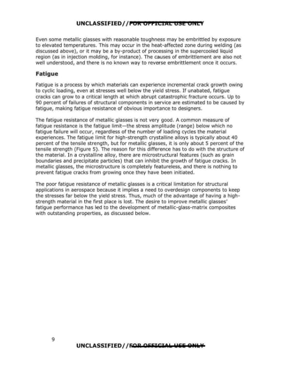
Report states metallic glass fatigue limit is about 5 percent of tensile strength

  • Verbatim
    The poor fatigue resistance of metallic glasses is a critical limitation for structural applications in aerospace
    DOW-UAP-D117 · Release 06 · page 15 · war.gov ↗
  • Verbatim
    for metallic glasses, it is only about 5 percent of the tensile strength (Figure 5).
    DOW-UAP-D117 · Release 06 · page 15 · war.gov ↗
  • Context

    The page compares this with about 40 percent for high-strength crystalline alloys, per the page summary.

New or already public? No matching pages in earlier releases.

Page by page

The pages and what the AI read on them

The transcription is the page reader's: black bars mark what the government redacted; hatched tags mark personal data we removed.

Page 13

Page 13 of 30

This is page 7 of an AAWSAP DIRD report on metallic glasses for aerospace applications, containing Table 2 comparing yield strengths of amorphous and crystalline aluminum alloys and a discussion of why metallic glasses fracture in a brittle manner. The page contains no redactions.

UNCLASSIFIED/ /FOR OFFICIAL USE ONLY Table 2. Comparison of Strengths of Amorphous and Crystalline Aluminum Alloys. Compared with the theoretical maximum strength (taken to be µ/30, where µ is the shear modulus of pure aluminum). | Yield Stress (MPa) | % of Theoretical Strength Theoretical Strength (Defect-Free Crystal) | 1,600 | - Typical High-Strength Aluminum Alloy (7xxx Series) 11 | 400-500 | 25-31% Best Crystalline Aluminum Alloy 12 | 770 | 48% Aluminum-Based Metallic Glass 13 | 1,280 | 80% Unfortunately, the lack of dislocations in amorphous alloys is also their Achilles' heel. In crystalline alloys, dislocations move and multiply in response to applied stresses, resulting in dislocation tangles that increase the resistance to further dislocation motion. This process, called strain hardening, is of crucial importance because it makes plastic deformation stable. If one region of a crystalline material yields and begins to plastically deform, the deforming region strain hardens, and so another region will deform instead. The result is that the plastic deformation is not concentrated but rather spreads through a large volume of material. Metallic glasses, lacking dislocations, do not strain harden and in fact strain soften in response to plastic deformation. This means that as soon as any one region yields, any further deformation will occur in the same region. This process, known as shear localization, leads to the formation of shear bands (Figure 4). In any loading geometry where the metallic glass experiences significant tensile loading, fracture occurs on a single dominant shear band with essentially zero tensile ductility. 2 Metallic glasses therefore fracture in an abrupt, apparently brittle manner on the macroscopic scale (even though there can be significant plasticity on a microscopic scale). This lack of ductility is of obvious concern to designers interested in structural applications. Furthermore, it limits the ability to fabricate metallic glasses into different shapes by deformation processing (by rolling or forging, for instance) after casting. 2 This assumes there is no geometrical constraint preventing fracture. Some geometries (such as simple bending) can involve tensile loading, but there can still be significant plastic deformation because the geometrical constraints inhibit propagating of shear bands across the specimen. 7 UNCLASSIFIED/ /FOR OFFICIAL USE ONLY
Page 14

Page 14 of 30

A page from a 2009 metallic glasses report, containing a figure of shear bands in a zirconium-based metallic glass and a section on fracture toughness comparing metallic glasses with crystalline alloys and ceramics. The page carries UNCLASSIFIED//FOR OFFICIAL USE ONLY markings at the top and bottom.

UNCLASSIFIED//FOR OFFICIAL USE ONLY Figure 4. Shear Bands. Produced by bending of a zirconium-based metallic glass.14 Fracture Toughness Fracture toughness is a measure of a material's resistance to growth of cracks, a critical property for structural materials subjected to tensile loading. In very tough metals, the toughness usually results from plastic deformation that occurs near the tip of the advancing crack; plastic deformation requires energy, and the need to provide this energy translates into resistance to crack growth.3 Despite their lack of tensile ductility, at least some metallic glasses are not brittle in the same sense that ceramics are, for example, because they can experience significant plastic deformation around the crack tip during fracture. For instance, the fracture toughness (Kic) of zirconium-based metallic glasses is about 20 MPa·m1/2 15\u2014somewhat lower than the ~ 55 MPa·m1/2 typical of crystalline zirconium alloys16 but much greater than the fracture toughness of ceramics (typically 1-5 MPa·m1/2). The fact that metallic glasses are reasonably tough despite their lack of tensile ductility suggests structural applications are not out of the question. However, some metallic glasses appear to be intrinsically brittle in that they fracture with only limited plastic deformation near the crack top and thus have very low values of fracture toughness. For this reason, some alloys that would otherwise be highly desirable, such as iron-based metallic glasses (for their high strength and low cost) and magnesium-based glasses (for their low density), fall into this category. The physical origins of the difference between intrinsically brittle metallic glasses and those capable of limited plastic deformation (and thus some toughness) are not well understood. 3 In other materials, notably polymer-matrix composites, other mechanisms of toughening can be more important. 8 UNCLASSIFIED//FOR OFFICIAL USE ONLY
Page 15

Page 15 of 30

Page 9 of a report on metallic glasses for aerospace applications, covering embrittlement at elevated temperatures and the poor fatigue resistance of metallic glasses compared with crystalline alloys. The page states that metallic glasses have a fatigue limit of about 5 percent of tensile strength versus about 40 percent for high-strength crystalline alloys.

UNCLASSIFIED//FOR OFFICIAL USE ONLY Even some metallic glasses with reasonable toughness may be embrittled by exposure to elevated temperatures. This may occur in the heat-affected zone during welding (as discussed above), or it may be a by-product of processing in the supercooled liquid region (as in injection molding, for instance). The causes of embrittlement are also not well understood, and there is no known way to reverse embrittlement once it occurs. Fatigue Fatigue is a process by which materials can experience incremental crack growth owing to cyclic loading, even at stresses well below the yield stress. If unabated, fatigue cracks can grow to a critical length at which abrupt catastrophic fracture occurs. Up to 90 percent of failures of structural components in service are estimated to be caused by fatigue, making fatigue resistance of obvious importance to designers. The fatigue resistance of metallic glasses is not very good. A common measure of fatigue resistance is the fatigue limit—the stress amplitude (range) below which no fatigue failure will occur, regardless of the number of loading cycles the material experiences. The fatigue limit for high-strength crystalline alloys is typically about 40 percent of the tensile strength, but for metallic glasses, it is only about 5 percent of the tensile strength (Figure 5). The reason for this difference has to do with the structure of the material. In a crystalline alloy, there are microstructural features (such as grain boundaries and precipitate particles) that can inhibit the growth of fatigue cracks. In metallic glasses, the microstructure is completely featureless, and there is nothing to prevent fatigue cracks from growing once they have been initiated. The poor fatigue resistance of metallic glasses is a critical limitation for structural applications in aerospace because it implies a need to overdesign components to keep the stresses far below the yield stress. Thus, much of the advantage of having a high-strength material in the first place is lost. The desire to improve metallic glasses' fatigue performance has led to the development of metallic-glass-matrix composites with outstanding properties, as discussed below. 9 UNCLASSIFIED//FOR OFFICIAL USE ONLY
Page 16

Page 16 of 30

A printed technical report page, numbered 10, containing a fatigue-limit chart for metallic glasses and composites and text on wear resistance and corrosion of metallic glasses. The page carries a FOR OFFICIAL USE ONLY marking and no redactions are visible.

UNCLASSIFIED//FOR OFFICIAL USE ONLY Figure 5 chart (see summary): y-axis labeled "Stress amplitude/Ultimate tensile strength" with ticks 0.01, 0.1, 1; x-axis labeled "Number of cycles to failure" with ticks 10^3 to 10^8. Curve labels: "Dendritic composite", "High-strength steel", "Single-phase metallic glass". Figure 5. Fatigue Limit of Metallic Glasses and Metallic-Glass-Matrix Composites. Fatigue life data for single-phase zirconium-based metallic glass (red) and a dendritic metallic glass matrix composite (blue). Representative data for steel (300-M) of similar tensile strength are shown for comparison. 17 18 19 Wear Resistance Because of their high yield strength, metallic glasses also have very high hardness. This, in turn, implies they might have good tribological behavior, which would be of particular interest when combined with the good corrosion resistance of some alloys (see below), opening up potential applications such as coatings on dry bearings for space applications. 20 However, the tendency of metallic glasses to form shear bands and (in some cases) partially crystallize owing to deformation means their wear resistance is perhaps not as good as their high hardness would suggest. Nevertheless, the wear resistance of metallic glasses can still be quite good, and in fact one of the principal current markets for amorphous alloys is as wear- and corrosion-resistant coatings for tools such as drill bits. Corrosion and Stress-Corrosion Cracking It is frequently stated that metallic glasses have excellent corrosion resistance, but this is not always true. The lack of grain boundaries and second-phase particles makes some metallic glasses extremely resistant to corrosion, but this is not true of all alloys (some of which oxidize rapidly in air). Broadly speaking, the corrosion resistance of nickel- and iron-based metallic glasses is better than that of alloys based on zirconium, titanium, and copper (particularly in environments containing chloride ions). 21 Some alloys are susceptible to localized pitting corrosion, probably facilitated by the presence of crystalline inclusions. 10 UNCLASSIFIED//FOR OFFICIAL USE ONLY
Page 17

Page 17 of 30

A page from a technical report on metallic glasses covering stress-corrosion cracking literature and mechanical behavior at elevated temperature, with Figure 6, a deformation map for metallic glasses. The text states that strength drops and deformation becomes homogeneous at high temperature, and that crystallization tendency precludes structural use near the glass transition temperature.

UNCLASSIFIED//FOR OFFICIAL USE ONLY The subject of stress-corrosion cracking of metallic glasses, despite its obvious importance for structural applications, has received scant attention in the literature. What little work that has been done has focused on zirconium-based glasses, with the observation that these alloys are very susceptible to stress-corrosion cracking in aqueous environments containing chloride ions, likely owing to the fact that they do not form protective oxide surface layers. 22 Mechanical Behavior at Elevated Temperature The discussion above relates to mechanical behavior at temperatures well below the glass transition temperature. At elevated temperatures, the strength drops and plastic deformation transitions to a homogeneous mode, occurring throughout the specimen instead of being localized into shear bands (Figure 6). Above the glass transition temperature, the alloy becomes a fluid, with a viscosity that drops exponentially with increasing temperature. Because the strength of the material is low, temperatures either above or below the glass transition may be useful for processing, as discussed above. However, the decrease in strength and the tendency for crystallization at elevated temperatures preclude use of metallic glasses from structural applications at temperatures approaching the glass transition temperature. [Figure 6 chart: y-axis Normalized stress, τ/μ (10^-3 to 10^-1); right axis Shear stress at 300 K (GPa) 0.1 to 1; x-axis T/Tg 0.4 to 1.2. Regions labeled: Inhomogeneous deformation (shear localization); Elastic (negligible flow); Non-Newtonian; Homogeneous deformation; Newtonian. Dashed strain-rate lines labeled 10^-10, 10^-6, 10^-3, 1 s^-1.] Figure 6. Deformation Map for Metallic Glasses. As a function of temperature (normalized to the glass transition temperature) and applied shear stress τ (normalized to the shear modulus, μ). At high stresses, plastic deformation occurs inhomogeneously, being localized into shear bands. At high temperatures, plastic deformation becomes homogeneous. The dashed lines represent different strain rates. The absolute stresses given are representative of the well-studied bulk metallic glass Zr41.2Ti13.8Cu12.5Ni10Be22.5, but the general features of the map are expected to apply to all metallic glasses.23 11 UNCLASSIFIED//FOR OFFICIAL USE ONLY
Page 18

Page 18 of 30

Page 12 of a 2009 AAWSAP DIRD report on metallic glasses, describing their magnetic, electrical, thermal, acoustic and optical properties. The page states that metallic glasses are highly reflective rather than transparent.

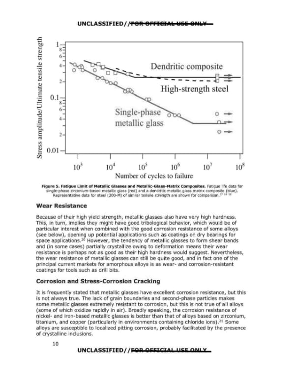
UNCLASSIFIED//FOR OFFICIAL USE ONLY Other Properties: Magnetic, Electrical, Optical, Thermal, and Acoustic Although most of the current interest in metallic glasses centers on their mechanical properties, it is appropriate to consider other properties of potential utility. Of these, the magnetic properties of ferromagnetic metallic glasses stand out.24 A variety of ferromagnetic glass-forming alloys exist, mostly based on transition metals (iron, nickel, and cobalt). The presence of alloying elements (necessary to make the material glass-forming) means the saturation magnetization of metallic glasses is not as large as that of the pure elements. However, some amorphous alloys have very low coercivity (a measure of how strong a magnetic field must be to change the direction of magnetization of the material) owing to the lack of crystalline defects (such as grain boundaries) and magnetocrystalline anisotropy. In addition, the relatively high electrical resistivity of amorphous alloys (see below) minimizes eddy current losses caused by high-frequency magnetization/demagnetization. Some amorphous alloys also have strong magnetoelastic effects (coupling between magnetic properties such as susceptibility or magnetization and elastic strain). Current and potential future applications of these magnetic properties are discussed below. Like crystalline alloys, metallic glasses have conduction electrons that make them both electrically and thermally conductive,25 although their structural disorder and high alloy content make them poor conductors. In addition, in a behavior that is useful in some applications, the conductivity of metallic glasses is not very sensitive to temperature; an exception is near absolute zero, where some amorphous alloys become superconducting. Another consequence of the amorphous structure of metallic glasses is that they tend to have very low acoustic damping. This may be useful in applications such as vibrating-structure gyroscopes for vehicle orientation.26 A common misperception among those hearing about metallic glasses for the first time is to think they are transparent. This is not the case; amorphous alloys are highly reflective, with a shiny luster similar to that of other metals (Figure 7). This is a result of the presence of the conduction electrons, which scatter and absorb incident light. 12 UNCLASSIFIED//FOR OFFICIAL USE ONLY
Page 19

Page 19 of 30

Page 13 of a report on metallic glasses, showing a photograph of a cast metallic glass wedge beside a ruler with Figure 7 caption, followed by text introducing metallic glass matrix composites and describing ex situ and in situ processing. The page carries FOUO markings at top and bottom.

UNCLASSIFIED//FOR OFFICIAL USE ONLY [Photograph: cast metallic glass wedge beside a metal ruler, scale marks 0 to 3 visible in inches and cm] Figure 7. Cast Metallic Glass Wedge. Wedge of a zirconium-based bulk metallic glass produced by casting. Note the shiny metallic luster, typical of metallic glasses. 27 Metallic Glass Matrix Composites As discussed above, the lack of crystalline defects gives metallic glasses high strength but compromises their ductility and fracture toughness. In particular, the tendency for plastic deformation to localize into shear bands prevents the material from deforming in a "graceful" manner. So it should not be surprising that there have been many attempts to control shear band initiation and propagation by making composite materials consisting of particles or fibers of some other material (most commonly a ductile crystalline metal) in a metallic glass matrix. The idea is to produce a material with improved ductility, fracture toughness, and fatigue properties while (hopefully) not sacrificing the qualities —especially strength and processing flexibility—that make metallic glasses interesting in the first place. PROCESSING AND STRUCTURE OF COMPOSITES Broadly speaking, there are two kinds of metallic glass matrix composites: ex situ and in situ. In ex situ composites, the metallic glass and the crystalline phase (be it in the form of particles or fibers) are physically combined, for instance by adding particles to the melt before casting. In situ composites are different in that the crystalline phase is produced directly from the melt (by precipitation) during processing. This fundamental difference in processing leads to significant differences in structure and therefore in properties. 13 UNCLASSIFIED//FOR OFFICIAL USE ONLY
Page 20

Page 20 of 30

This page from a 2009 AAWSAP DIRD report on metallic glasses describes two methods of making ex situ composites and the limitations of each, then introduces in situ composites in which the crystalline phase precipitates from the melt. It is a technical discussion with no redactions.

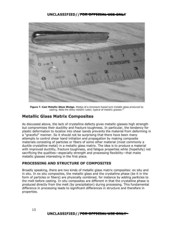
UNCLASSIFIED//FOR OFFICIAL USE ONLY EX SITU COMPOSITES There are two basic ways of making ex situ composites, in which the metallic glass matrix and the crystalline phase are combined physically, without a chemical reaction: • Add crystalline particles to a melt of a glass-forming alloy and then cast under conditions that allow the matrix to form a metallic glass. • Make a preform of a crystalline phase (by packing fibers into a mold, for instance) and then cast the glass-forming alloy around the preform. Both approaches have limitations. In the first, the addition of particles to the melt increases the viscosity (which is already quite high relative to non-glass-forming alloys) considerably, ultimately to a point where casting becomes impossible. This limits the volume fraction of particles that can be added, which in turn limits the control one has over the microstructure and, in particular, the spacing of the particles. With a preform, the volume fraction of the crystalline phase can be much higher (up to about 80 percent by volume), but the problem then is how to infiltrate the high-viscosity melt into the preform without leaving voids and while still ensuring sufficiently rapid cooling to form a glassy matrix. With both approaches, interfacial reactions between the crystalline phase and the melt can cause partial or complete crystallization of the matrix, degrading the mechanical properties. IN SITU COMPOSITES The difficulty of making satisfactory ex situ composites has led to the development of a new approach in which the crystalline phase is precipitated directly from the melt, either during casting28 or in a separate step prior to casting. 29 30 Precipitation during casting, although easier, is problematic from a practical standpoint because variations in the cooling rate (from the surface to the center of a casting, for instance) lead to significant variations in structure and, hence, in properties. One of the most promising recent advances in the metallic glass field is the development of in situ composites in which the crystalline phase is precipitated as dendrites, either during casting (Figure 8) or by holding the alloy at an elevated temperature prior to casting. 31 By suitably choosing alloy composition, holding time, and temperature, the volume fraction, size, and spacing of the dendritic phase can be controlled. This control provides great flexibility in determining the mechanical properties of the resulting material. Because the crystalline phase is produced prior to casting, variation in the cooling rate across the casting is much less important, though the cooling rate must still be sufficiently high to ensure the matrix forms a glass during cooling. Once the glassy matrix is formed, the composite can be reheated above the glass transition temperature, allowing for thermoplastic forming in a manner similar to single-phase metallic glasses (as described above). Finally, the presence of the dendritic second phase allows for deformation processes (for example, by cold rolling or forging), similar to crystalline alloys. 32 14 UNCLASSIFIED//FOR OFFICIAL USE ONLY
Page 21

Page 21 of 30

A page from a technical report on metallic glass matrix composites, containing a figure with two micrographs of dendrites in a glassy matrix and text on the limits of in situ composite alloy systems and the mechanical properties and plastic zone size of these composites.

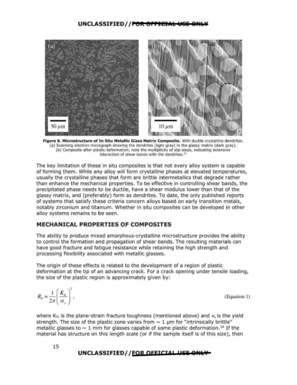
UNCLASSIFIED//FOR OFFICIAL USE ONLY Figure 8. Microstructure of In Situ Metallic Glass Matrix Composite. With ductile crystalline dendrites. (a) Scanning electron micrograph showing the dendrites (light gray) in the glassy matrix (dark gray). (b) Composite after plastic deformation; note the multiplicity of slip steps, indicating extensive interaction of shear bands with the dendrites.33 The key limitation of these in situ composites is that not every alloy system is capable of forming them. While any alloy will form crystalline phases at elevated temperatures, usually the crystalline phases that form are brittle intermetallics that degrade rather than enhance the mechanical properties. To be effective in controlling shear bands, the precipitated phase needs to be ductile, have a shear modulus lower than that of the glassy matrix, and (preferably) form as dendrites. To date, the only published reports of systems that satisfy these criteria concern alloys based on early transition metals, notably zirconium and titanium. Whether in situ composites can be developed in other alloy systems remains to be seen. MECHANICAL PROPERTIES OF COMPOSITES The ability to produce mixed amorphous-crystalline microstructure provides the ability to control the formation and propagation of shear bands. The resulting materials can have good fracture and fatigue resistance while retaining the high strength and processing flexibility associated with metallic glasses. The origin of these effects is related to the development of a region of plastic deformation at the tip of an advancing crack. For a crack opening under tensile loading, the size of the plastic region is approximately given by: Rp ≈ (1/2π)(K_Ic/σy)^2, (Equation 1) where KIc is the plane-strain fracture toughness (mentioned above) and σy is the yield strength. The size of the plastic zone varies from ~1 µm for "intrinsically brittle" metallic glasses to ~1 mm for glasses capable of some plastic deformation.34 If the material has structure on this length scale (or if the sample itself is of this size), then 15 UNCLASSIFIED//FOR OFFICIAL USE ONLY
Page 22

Page 22 of 30

A report page on metallic glass matrix composites, covering plastic deformation, strength and ductility, fracture and fatigue, and the start of a section on structural aerospace applications. It reports tensile elongation up to 12 percent for titanium-based in situ composites and fracture toughness above 170 MPa m1/2 for some zirconium-based composites.

UNCLASSIFIED//FOR OFFICIAL USE ONLY deformation can proceed in a stable manner by generation and subsequent arrest of shear bands. The key to composite design is to produce a microstructure with the correct length scale to prevent propagating shear bands from becoming catastrophic cracks. This turns out to be relatively difficult with ex situ composites, for reasons of processing described above. As a result, the recently developed dendritic in situ composites have the most promising properties, and we focus the remainder of our discussion on them. STRENGTH AND DUCTILITY: PLASTIC DEFORMATION As with other composite materials, the yield strength of metallic glass matrix composites can be approximated as a simple rule of mixtures based on the volume fraction of the two phases. Because the ductile crystalline phases useful for limiting shear band propagation are weaker than the amorphous matrix, in producing a composite, some sacrifice in strength is inevitable. However, the gains in tensile ductility can be significant. For instance, monolithic titanium-based metallic glasses (like all metallic glasses) have essentially zero tensile ductility, but in situ composites based on titanium have been reported with tensile elongation as large as 12 percent. 35 This is comparable to the ductility of Ti-6Al-4V (the most common conventional titanium alloy), but in a material with about 30 percent greater strength. The properties of metallic glass matrix composites and more conventional materials are further compared below. FRACTURE AND FATIGUE The development of a stable plastic zone means additional energy is required for crack propagation, making in situ composites much more resistant to fracture and fatigue than are single-phase glasses. For instance, the plane-strain fracture toughness of some zirconium-based in situ composites can exceed 170 MPa m1/2 7 times greater than that of single-phase glasses and greater than that of virtually any other metallic alloy. 36 This resistance to crack propagation is also manifested as improved fatigue performance. The fatigue strength of the zirconium-based in situ composites is 20-30 percent of the tensile strength; in comparison, monolithic metallic glasses have a fatigue strength of only ~ 5 percent of the tensile strength. 37 The fatigue strength of the in situ composites is thus comparable to that of conventional structural alloys. Aerospace Applications of Metallic Glasses STRUCTURAL APPLICATIONS The key properties of materials for structural applications in aerospace are: • Strength. • Stiffness (Young's modulus). • Density (weight). • Fracture toughness (damage tolerance). 16 UNCLASSIFIED//FOR OFFICIAL USE ONLY
Page 23

Page 23 of 30

A page of a report on metallic glasses and metallic glass matrix composites, discussing fatigue, corrosion and cost criteria, mechanical property comparisons in Figure 9, and potential aerospace applications. Marked UNCLASSIFIED//FOR OFFICIAL USE ONLY with page number 17.

UNCLASSIFIED//FOR OFFICIAL USE ONLY • Fatigue resistance (including resistance to both fatigue crack initiation and fatigue crack growth). • Corrosion resistance (including stress-corrosion cracking). • Cost (including raw materials, shaping, and assembly). Figure 9 illustrates the mechanical properties of metallic glasses and metallic glass matrix composites compared with other structural materials. Since weight is a particular concern in aerospace applications, in Figure 9(a) we normalize both yield strength (σy) and stiffness (E) to density (ρ); two materials with the same specific strength (σy /ρ) or specific stiffness (E/ρ) could be used to produce a component with the same overall strength or stiffness, respectively, at the same weight. Materials in the upper-right corner of the plot have the best combination of strength and stiffness for a given weight. Notice that the metallic glasses (and dendritic composites) can be stronger than virtually all crystalline metals, although the stiffness of metallic glasses tends to be somewhat smaller than that of crystalline alloys of similar composition. Figure 9(b) illustrates the damage tolerance of metallic glasses compared with other materials. By plotting the fracture toughness (KIc) against modulus (E), we can also compare the fracture energy (GIc ≈ (KIc)2/E) of the materials; the dashed diagonal lines are lines of constant fracture energy. Figure 9(b) reveals several interesting aspects of the damage tolerance of metallic glasses. First, although the fracture toughness of some metallic glasses is comparable to that of crystalline metals, some metallic glasses—most notably those based on iron (Fe) and magnesium (Mg)—are as brittle as any ceramic. Second, both the fracture toughness and the fracture energy of the dendritic metallic glass matrix composites can be superior to those of all but the most fracture-resistant metals. These considerations suggest the dendritic metallic glass matrix composites might indeed find applications as structural materials in aircraft and/or spacecraft. The most obvious applications would be to replace steel in certain components where strength is critical but space is limited. These might include pylon structures and landing gear,38 although it has yet to be demonstrated that the composites can be fabricated in the sizes necessary. Furthermore, the corrosion and stress-corrosion cracking resistance of these materials has not been fully evaluated. 17 UNCLASSIFIED//FOR OFFICIAL USE ONLY
Page 24

Page 24 of 30

A materials property chart page from an AAWSAP DIRD report on metallic glasses, showing two plots of strength versus stiffness and fracture toughness versus stiffness for various materials, with a figure caption. The header and footer carry UNCLASSIFIED//FOR OFFICIAL USE ONLY markings.
UNCLASSIFIED//FOR OFFICIAL USE ONLY Silicon carbide 0.1 ... bl) 0 ,0! d (I) l;j Vl u (.0 ...... <.) Q) 0.. 0.00 1 C/) Spe ifi tiffn s , E/p MPa m kg- 1 a Metallic gJas Dendrili c a \ _ compo ites ~~e Wood Aluminum O Alumlna p lym rs (aloog grain) lilnnlum 0 0 0.1 lO lO . 100 (I.) (/J Q) C: .c 10 b l} :;j 0..... Q.) I-; 2 (..) Cd i... u.. Figure 9. Materials Property Charts. (a) Strength and stiffness (both normalized to density) of metallic glasses (yellow) and dendrltic metall ic glass matrix composites (red) compared with other materials. (b) Damage tolerance. On this plot, the dashed lines represent contours of equal fracture energy. In both plots, polymer composites (CFRP and GFRP) are represented by Isotropic averages; continuous fiber composites can have greater strength and stiffness In a direction parallel to the flbers .39 18 UNCLASSIFIED//FOR OFFICIAL USE ONLY / Pol Stiffne (b) ~<" ✓ r, t",sF/ Dcndritic c mpo ite Low lloy steels Nick I-based superalloys Hardwood (along grain) 10 100 E (GPa) 1000